Connector pin shrinkage detection device and detection method

A detection device and connector technology, applied in the direction of measuring device, measuring device casing, using optical device, etc., can solve the problem of poor stability of force generated by elastic deformation, unconfirmed feed amount of three-dimensional moving mechanism, and unable to guarantee the applied force and constant force And other issues

Pending Publication Date: 2020-10-23
NINGBO CRRC TIMES TRANSDUCER TECH CO LTD
View PDF6 Cites 7 Cited by
  • Summary
  • Abstract
  • Description
  • Claims
  • Application Information

AI Technical Summary

Problems solved by technology

However, in the actual working process, the acting constant force is generated by the elastic deformation of the compression elastic device, and the stability of the force generated by the elastic deformation is relatively poor, and it may be caused by the performance change of the compression elastic device itself during long-term use. The magnitude of the constant force generated corresponding to the feed rate changes, and the specific magnitude of the applied force cannot be confirmed during the entire working process, that is, the applied force cannot be guaranteed to be the set constant force
In addition, it is not possible to confirm whether the feed rate of the three-dimensional moving mechanism is standard.

Method used


Image

  • Connector pin shrinkage detection device and detection method
  • Connector pin shrinkage detection device and detection method
  • Connector pin shrinkage detection device and detection method

Examples


Embodiment Construction

[0040] The present invention will be further described in detail below in conjunction with the accompanying drawings and embodiments.

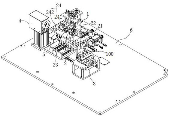
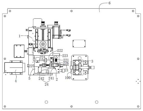
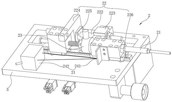
[0041] like Figure 1 to Figure 4 As shown, the connector pin shrinkage detection device in this embodiment includes a host computer, a three-dimensional movement mechanism 1, a needle shrinkage detection mechanism 2, a clamping mechanism 3, and a visual positioning mechanism 4. In this embodiment, the connector The needle insertion shrinkage detection device also includes a frame platform 6 on which at least the three-dimensional moving mechanism 1 , the clamping mechanism 3 and the visual positioning mechanism 4 are installed.

[0042]Wherein, the upper computer can adopt a control unit configured directly as one, and the control unit can include a control chip, a control circuit electrically connected to the control chip, a display, operation keys, and the like. The upper computer can also be set as an external computer.

[0043] The thre...


PUM


Abstract

The invention relates to a connector pin shrinkage detection device which comprises an upper computer; a three-dimensional moving mechanism electrically connected with the upper computer; a pin shrinkage detection mechanism connected with the three-dimensional moving mechanism; a clamping mechanism arranged on one side of the pin shrinkage detection mechanism; and a visual positioning mechanism arranged relative to the clamping mechanism and electrically connected with the upper computer and used for detecting the position of each contact pin in the connector. The pin shrinkage detection mechanism comprises a pin detection probe, a driving mechanism used for driving the pin detection probe to apply force, a pressure sensor connected between the driving end of the driving mechanism and thepin detection probe, and a displacement detection mechanism used for detecting the retraction distance of a pin. The driving mechanism, the pressure sensor and the displacement detection mechanism areelectrically connected with the upper computer. The invention also relates to a connector pin shrinkage detection method. According to the connector pin shrinkage detection device and method, the magnitude of the acting force acting on the contact pin can be obtained in real time, the acting force on the contact pin can be controlled more accurately, and the accuracy of the detection result is improved.

Description

technical field [0001] The invention relates to a connector pin shrinkage detection device, and also relates to a detection method of the connector pin shrinkage detection device. Background technique [0002] Connector installation is to insert the pin of the connector into the mounting hole of the connector head. The tail of the pin has a barbed structure. When it is installed in place, it will be stuck in the mounting hole of the connector head so that the pin will not fall off. Therefore, there are two main requirements for the installation of the connector. One is that the pins must be installed in place, and the other is that it must be able to withstand a certain thrust. If the pins are not seated properly, the barbed structure will not work, will not withstand a certain amount of thrust and will not make good contact with the device it is connected to. If the pin cannot withstand a certain thrust, then in actual use, when it is connected to other devices, the pin wi...

Claims


Application Information

Patent Timeline
Patent Type & Authority Applications(China)
IPC IPC(8): G01R31/00G01R1/04G01N21/84G01N21/01G01M13/00G01L5/00G01B11/02
CPCG01R31/00G01R1/04G01N21/84G01N21/01G01B11/02G01M13/00G01L5/0038
Inventor 刘佳陈军张聪罗桂平廖伟龙洪振惠
Owner NINGBO CRRC TIMES TRANSDUCER TECH CO LTD
Why Eureka
Try Eureka