
Display device

A display device and display area technology, applied in the directions of light guides, optics, instruments, etc., can solve the problems of inability to supplement the brightness value of the edge of the display area, abnormal light leakage at the edge of the display area, etc.

Active Publication Date: 2020-10-23
CORETRONIC DISPLAY SUZHOU CO LTD
View PDF3 Cites 4 Cited by
  • Summary
  • Abstract
  • Description
  • Claims
  • Application Information

AI Technical Summary

Problems solved by technology

However, part of the light beam emitted from the side edge of the light guide plate is (diffusely) reflected by the white plastic frame, which easily leads to abnormal light leakage at the edge of the display area under side viewing angles.
Conversely, when the color of the plastic frame is black, it cannot complement the luminance value at the edge of the display area, resulting in the formation of dark lines (or dark lines) at the edge of the display area

Method used


Image

  • Display device
  • Display device

Examples


Embodiment Construction

[0012] The aforementioned and other technical contents, features and effects of the present invention will be clearly presented in the following detailed description of a preferred embodiment with reference to the accompanying drawings. The directional terms mentioned in the following embodiments, such as: up, down, left, right, front or back, etc., are only referring to the directions of the drawings. Accordingly, the directional terms are used to illustrate and not to limit the invention.

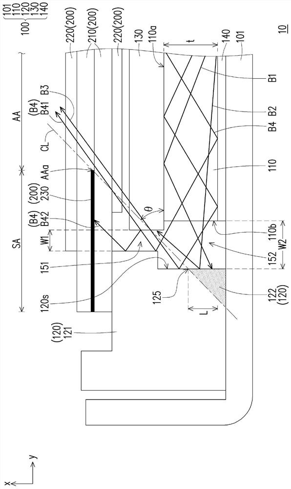
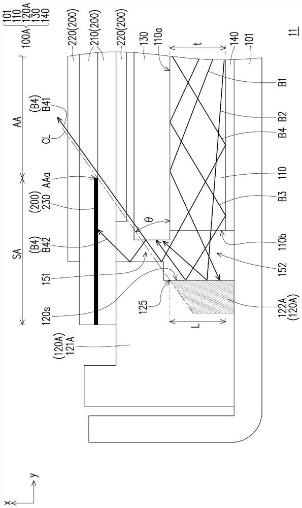
[0013] figure 1 is a schematic cross-sectional view of a display device according to an embodiment of the present invention. Please refer to figure 1 , the display device 10 includes a backlight module 100 and a display panel 200 , wherein the display panel 200 is disposed on the backlight module 100 . For example, after the light beam from the backlight module 100 passes through the display panel 200 , it can form an image light beam and transmit it to human eyes to generate a display...


PUM


Abstract

The invention provides a display device. The display device comprises a display panel, a light guide plate and a rubber frame. The display panel has a display area. The light guide plate overlaps thedisplay area and has a light emitting surface and a side wall connected to the light emitting surface. The rubber frame comprises a reflecting surface, a high-reflectivity material part and a low-reflectivity material part. The reflecting surface faces the side wall of the light guide plate. The high reflectance material portion is configured to bear the display panel. The low-reflectivity material part is connected to the high-reflectivity material part, and the reflectivity of the low-reflectivity material part is lower than the reflectivity of the high-reflectivity material part. At least one junction of the high-reflectivity material part and the low-reflectivity material part is arranged on the reflecting surface. At least one junction and the side edge of the display area are provided with a connecting line, and an included angle equal to or smaller than 45 degrees is formed between the connecting line and the light-emitting face. The display device provided by the invention is good in light emitting uniformity at different visual angles.

Description

technical field [0001] The present invention relates to a display device, and in particular to a display device with a backlight module. Background technique [0002] In recent years, with the development of display technology, consumer displays (such as smart TVs, e-sports displays) have not only improved display performance (such as ultra-high resolution, high contrast, high frame rate), but also their overall appearance (such as narrow Frame, thin) taste has gradually become one of the important indicators for consumers when purchasing. On the other hand, under the consideration of factors such as cost and service life, liquid crystal displays are still the majority of large-size displays. Since the liquid crystal display panel is a non-self-illuminating display panel, it needs to be used with a backlight module to display images. [0003] In general, backlight modules can be divided into direct-type backlight modules and side-type backlight modules according to the arr...

Claims


Application Information

Patent Timeline
IPC IPC(8): G02F1/1333G02F1/13357G02B6/00
CPCG02F1/133308G02F1/133608G02F1/133605G02F1/133606G02B6/0088
Inventor 叶君
Owner CORETRONIC DISPLAY SUZHOU CO LTD
Learn More