Step-down rectifier circuit and wireless charging control unit
A rectifier circuit and control unit technology, applied in electrical components, circuit devices, battery circuit devices, etc., can solve problems such as large size, large number of electrical components, and circuit damage.
- Summary
- Abstract
- Description
- Claims
- Application Information
AI Technical Summary
Problems solved by technology
Method used
Image
Examples
no. 1 example
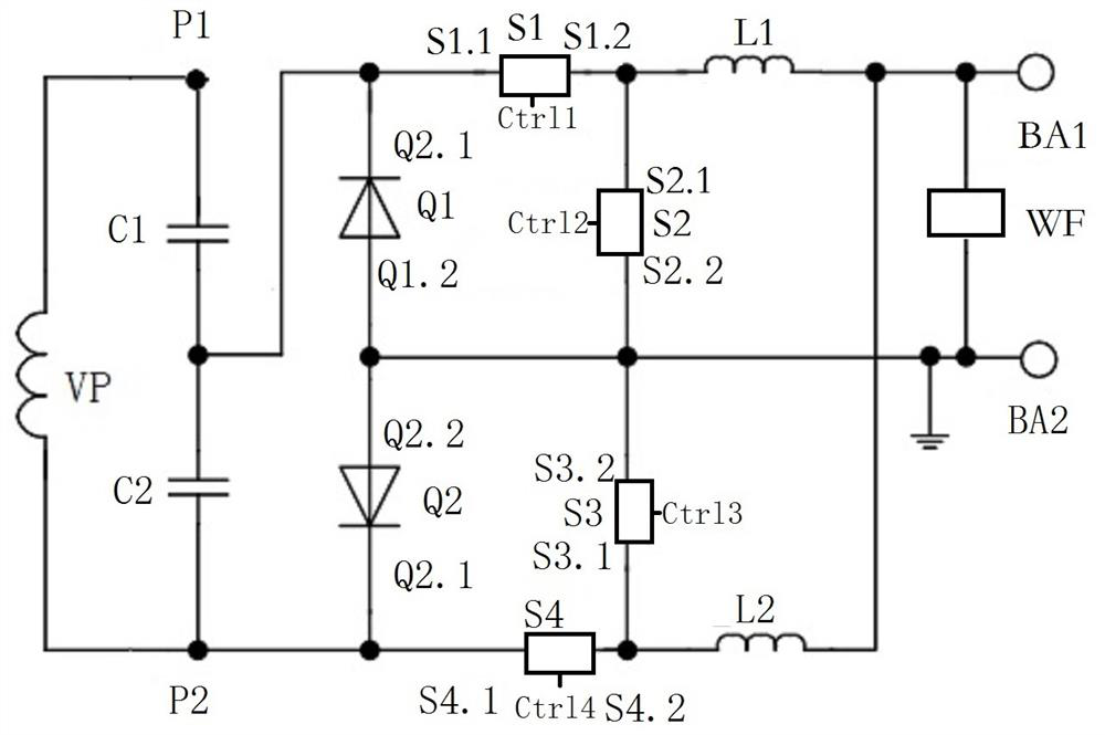
[0068] The first embodiment, such as figure 1 As shown, the present invention provides a step-down rectifier circuit, including:
[0069] The filter circuit WF is electrically connected between the first connection point BA1 and the second connection point BA2 of the charged storage device BA;
[0070] Filter switch structure one S1 connection point one S1.1 is electrically connected to resonant device one P1 connection point two P1.2, filter switch structure one S1 connection point two S1.2 is electrically connected to filter switch structure two S2 connection point one S2.1 is electrically connected to the connection point BA1 of the charged storage device BA through the inductor L1, and its control point is used as the control terminal Ctrl1 of the step-down rectification circuit;
[0071] The connection point 2 S2.2 of the filter switch structure 2 S2 is electrically connected to the connection point 2 Q1.2 of the rectifier device 1 Q1, the connection point 2 S3.2 of the...
no. 2 example
[0080] The second embodiment, continue to refer to figure 1 As shown, the present invention provides a step-down rectifier circuit, including:
[0081] The filter circuit WF is electrically connected between the first connection point BA1 and the second connection point BA2 of the charged storage device BA;
[0082] Filter switch structure one S1 connection point one S1.1 is electrically connected to resonant device one P1 connection point two P1.2, filter switch structure one S1 connection point two S1.2 is electrically connected to filter switch structure two S2 connection point one S2.1 is electrically connected to the connection point BA1 of the charged storage device BA through the inductor L1, and its control point is used as the control terminal Ctrl1 of the step-down rectification circuit;
[0083] The connection point 2 S2.2 of the filter switch structure 2 S2 is electrically connected to the connection point 2 Q1.2 of the rectifier device 1 Q1, the connection point...
no. 3 example
[0093] The third embodiment, such as Figure 6 As shown, the present invention provides a wireless charging control unit, including:
[0094] The vehicle-side induction coil VP is suitable for wireless current transmission with the wireless charging ground-side coil through electromagnetic induction;
[0095] Step-down rectification step-down rectification circuit RC, which is connected between the induction coil VP at the vehicle end and the charged storage device BA of the vehicle battery, which is driven by the DSP controller to provide different charging paths for the charged storage device (BA) of the vehicle battery )Charge;
[0096] DSP controller, before starting charging, it can judge whether the wireless charging ground coil and the vehicle induction coil are in place according to the working conditions of the vehicle-side induction coil and the vehicle-mounted battery to be charged storage device BA, and it can be charged according to the vehicle-mounted battery T...
PUM
 Abstract
Description
Claims
Application Information
 - R&D
- Intellectual Property
- Life Sciences
- Materials
- Tech Scout
- Unparalleled Data Quality
- Higher Quality Content
- 60% Fewer Hallucinations
Browse by: Latest US Patents, China's latest patents, Technical Efficacy Thesaurus, Application Domain, Technology Topic, Popular Technical Reports.
© 2025 PatSnap. All rights reserved.Legal|Privacy policy|Modern Slavery Act Transparency Statement|Sitemap|About US| Contact US: help@patsnap.com


