Ultrasonic guidance-based puncture device

An ultrasonic and guide head technology, applied in the medical field, can solve problems such as affecting the stability, falling and damage of the holding probe or puncture needle

Active Publication Date: 2020-10-27
QINGDAO MUNICIPAL HOSPITAL
View PDF9 Cites 3 Cited by
  • Summary
  • Abstract
  • Description
  • Claims
  • Application Information

AI Technical Summary

Problems solved by technology

[0003] The existing patent No. CN109567906B proposes a puncture needle and an ultrasonic puncture device, which has the advantage of reducing or even eliminating the mutual interference of various data/signals transmitted in the puncture needle, but when it is used, when the user needs to guide the When changing to in-plane guidance, the angle of the probe needs to be changed by 90 degrees. At this time, the puncture needle has been inserted into the patient’s skin. When the user changes t

Method used


Image

  • Ultrasonic guidance-based puncture device
  • Ultrasonic guidance-based puncture device
  • Ultrasonic guidance-based puncture device

Examples


Embodiment 1

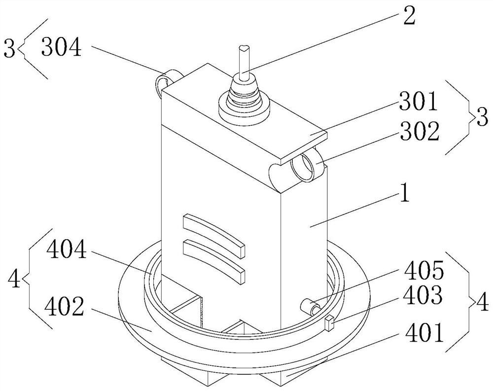
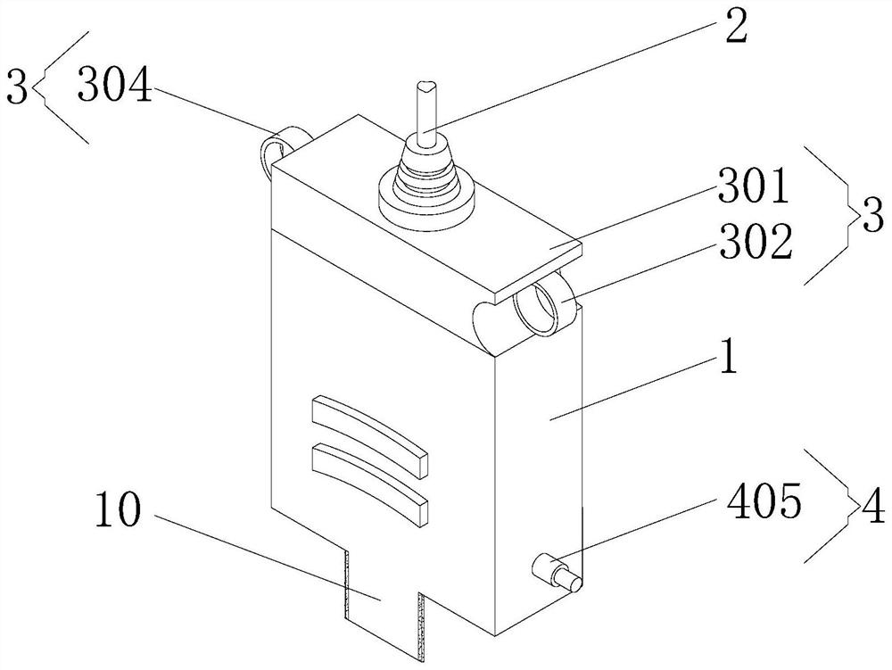
[0037] Example 1: Please refer to Figure 1-5 , a puncture device based on ultrasound guidance, including a probe 1, a cable 2, a holding member 3 and a contact member 4, the probe 1 is an ultrasonic transmitting end, and its internal structure is an existing known technology, so it will not be described here. The cable 2 is the power and signal line of the probe 1, the cable 2 is located at the center of the top of the probe 1, the holding part 3 is fixedly installed above the probe 1, and the contact part 4 is fixedly installed below the probe 1.

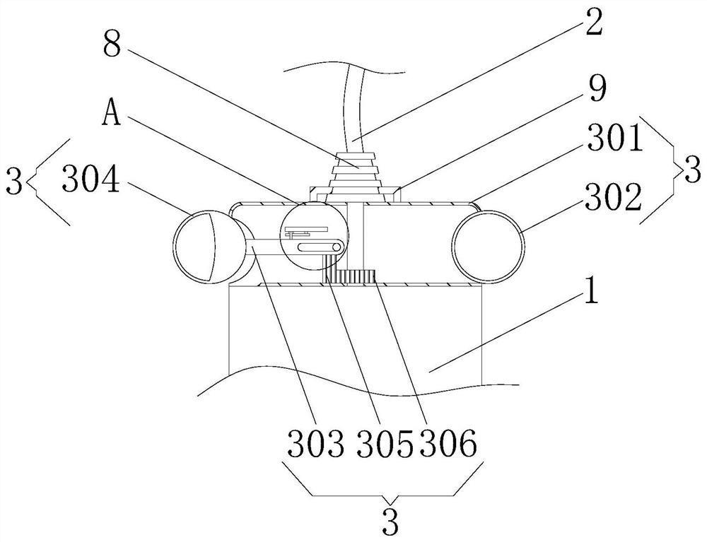
[0038] The holding part 3 includes a top base 301 and a long plate 303. The top base 301 is fixedly connected to the top surface of the probe 1. A hole is opened in the center of the top base 301 and is socketed with the cable 2. The inside of the top base 301 is hollowed out. The right side of the top base 301 is fixedly connected with an insert ring A302, the back inner wall on the left side of the top base 301 is provided with a ...

Embodiment 2

[0042] Example 2: Please refer to Figure 6-10 , On the basis of Embodiment 1, the outer wall of the bottom ring 402 is equidistantly provided with four cutting grooves 15, the guide mechanisms 13 are fixedly installed in the four cutting grooves 15, and the fixing mechanism 14 is fixedly installed inside the bottom ring 402.

[0043] The bottom ring 402 includes an inner ring 4021 and an outer ring 4022. The inner ring 4021 is sleeved on the inner wall of the outer ring 4022. The guide mechanism 13 includes a rotating rod 1301, a rotating plate 1302 and a socket 1303. Both sides of the inner wall of the cutting groove 15 are provided with It has a hole and is socketed with the rotating rod 1301. The side of the rotating rod 1301 away from the probe 1 is firmly connected with the rotating plate 1302. The top surface of the rotating plate 1302 is provided with a chute D16. Socket socket, the center of the insertion sleeve 1303 is in the form of a ring, and the diameters of the ...


PUM


Abstract

The invention relates to the technical field of medical treatment, and discloses an ultrasonic guidance-based puncture device. The ultrasonic guidance-based puncture device comprises a probe, a cable,a holding piece and a contact piece; the cable is located at the center of the top end of the probe; the holding piece is fixedly installed over the probe; the holding piece includes a top seat and along plate; the top seat is fixedly connected with the top face of the probe; a hole is formed in the center of the top seat and is connected with the cable in a sleeving manner; the interior of thetop seat is in a hollow state; the inner wall of the top seat is provided with a cylindrical protrusion; a sliding groove A is formed in the long plate; the inner wall of the sliding groove A is connected with the cylindrical protrusion in a sleeving manner; the long plate is fixedly connected with an insert ring B; the long plate is fixedly connected with a toothed plate; and the outer wall of the cable is fixedly connected with a toothed ring. By installing the holding piece, through separation and closing of fingers after holding, the probe can be driven to rotate with the cable as the axis, and thus, in the puncture process, the transition from out-of-plane guidance to in-plane guidance of a puncture needle does not require changing a hand position and lifting up the probe, thereby avoiding the problems of unstable holding and an awkward sitting posture caused by changing the hand position.

Description

technical field [0001] The invention relates to the field of medical technology, in particular to a puncture device based on ultrasound guidance. Background technique [0002] Ultrasound-guided puncture therapy is a technology that uses ultrasound emitted by equipment to display the patient's subcutaneous muscles and blood vessels and other organs, so as to guide the puncture of the puncture needle for treatment. Ultrasound-guided puncture needs to emit ultrasound through the probe corresponding to the patient's part, and then puncture The needle is punctured under the probe. [0003] The existing patent No. CN109567906B proposes a puncture needle and an ultrasonic puncture device, which has the advantage of reducing or even eliminating the mutual interference of various data / signals transmitted in the puncture needle, but when it is used, when the user needs to guide the When changing to in-plane guidance, the angle of the probe needs to be changed by 90 degrees. At this t...

Claims


Application Information

Patent Timeline
IPC IPC(8): A61B17/34
CPCA61B17/3403A61B2017/0042A61B2017/3413A61B2017/3492
Inventor 李梅于广兰孙灵杜卉
Owner QINGDAO MUNICIPAL HOSPITAL
Why Eureka
Try Eureka