Die for die casting

A mold and movable mold technology, applied in the field of die casting molds, can solve the problems of shrinkage deformation, difficult production and processing of the frame 1, poor stability of the frame structure, etc.

Pending Publication Date: 2020-10-27
SHANGHAI PRECISE IND
View PDF0 Cites 2 Cited by
  • Summary
  • Abstract
  • Description
  • Claims
  • Application Information

AI Technical Summary

Problems solved by technology

When using the existing mold to prepare the frame, the structural stability of the frame is poor, and the problem of shrinkage and deformation is prone to occur
When forming the frame 1 by die-casting, the flatness of each plane of the frame 1 formed by die-casting is all below 0.1, and even

Method used


Image

  • Die for die casting
  • Die for die casting
  • Die for die casting

Examples


Embodiment Construction

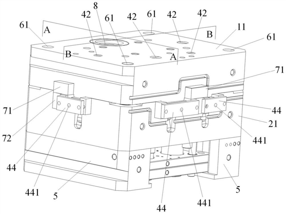
[0020] Below, combined with Figure 3-6 The mold for die casting of the present invention will be described in detail.

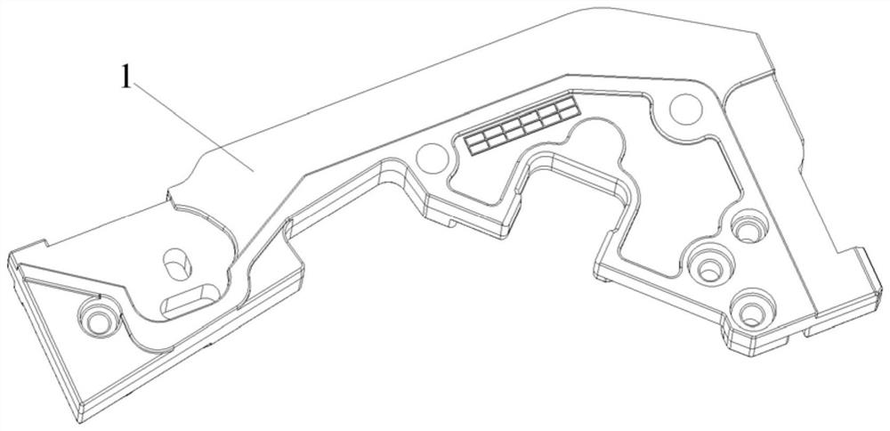
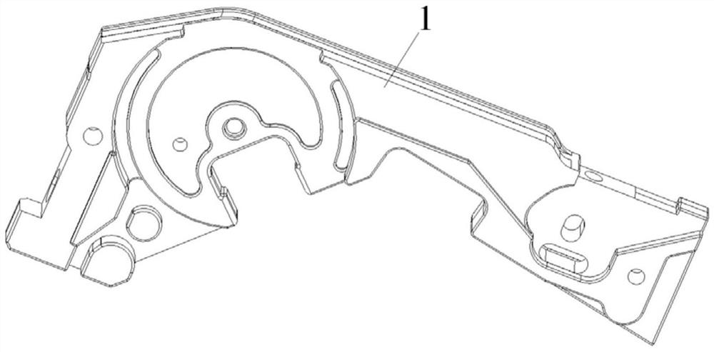
[0021] Such as Figure 3-6As shown, the mold for die-casting of the present invention includes a fixed mold, a movable mold, a mold foot and an exhaust mechanism. Die groove, and the fixed mold core 12 is provided with a mold cavity towards the fixed joint surface of the movable mold; , the movable mold core 22 is provided with a mold core and a plurality of slag ladle grooves 221 on the movable joint surface facing the fixed mould. During mould-closing, the core on the movable core 22 stretches into the corresponding cavity to form a cavity for die-casting to form the frame 3 . Preferably, two mold cores are arranged on the movable mold core 12, and a slag ladle groove 221 is respectively arranged at the two ends and the slope end of each mold core. When the runner 222 on the core 22 is poured into the mold cavity, the air in the runner 222 and the mold...


PUM


Abstract

The invention relates to the technical field of dies, and provides a die for die casting. The die for die casting aims to reduce the difficulty of frame producing and machining, improve the qualifiedrate of finished products, and is used for die casting production of the frame. In a fixed die, a mold cavity is formed in a fixed die core and is mounted in a fixed die groove in the middle of a fixed die plate. In a moving mold, a moving die core is provided with a mold core and a slag ladle groove and is mounted in a moving die groove in the moving die plate. The die core corresponds to the position of the mold cavity. The slag ladle groove is close to the end portion of the mold core. A die foot is located at the bottom of the moving die plate and is fixedly connected with the two ends ofthe moving die plate. In an exhausting mechanism, a fixed exhausting plate is mounted on and fixed to the fixed die plate, a moving exhausting plate is mounted on and fixed to the moving die plate, and a fixed exhausting groove in the moving exhausting plate communicates with the slag ladle groove. During die closing, the fixed exhausting plate is buckled with the moving exhausting plate, and a fixed exhausting groove in the fixed exhausting plate is in butt joint with a moving exhausting groove to form an exhausting channel. By using the die for die casting, deformation can be reduced, the machining difficulty is reduced, and the yield of finished products is improved.

Description

technical field [0001] The invention relates to the technical field of dies, in particular to a die-casting die. Background technique [0002] figure 1 and 2 The frame 1 shown is applied to electronic equipment. When the frame is prepared by using the existing mold, the structural stability of the frame is poor, and the problem of shrinkage and deformation is prone to occur. When forming the frame 1 by die-casting, the flatness of each plane of the frame 1 formed by die-casting is all below 0.1, and even the flatness of some individual planes is required to be below 0.05, and the processing requirements for its surface roughness and appearance are also very high. Strict, resulting in the production and processing of the frame 1 is difficult, and the qualified rate of finished products is low. Contents of the invention [0003] In order to reduce the production and processing difficulty of the frame and improve the qualified rate of finished products, the present invent...

Claims


Application Information

Patent Timeline
IPC IPC(8): B22D17/22
CPCB22D17/22B22D17/2218B22D17/2236B22D17/2272
Inventor 钱文龙张登峰周灵忠肖雪林叶勤良王建军
Owner SHANGHAI PRECISE IND
Why Eureka
Try Eureka