Separable bow structure of supercavitation underwater vehicle

A separate technology for underwater vehicles, applied to the hull bow, hull parts, ships, etc., can solve the problems of vehicle performance degradation, high pressure gradient, etc.

Active Publication Date: 2020-10-27
TIANJIN UNIV
View PDF8 Cites 8 Cited by
  • Summary
  • Abstract
  • Description
  • Claims
  • Application Information

AI Technical Summary

Problems solved by technology

Taking a supercavitating underwater vehicle equipped with a disc-shaped cavitator as an example, the disc-shaped cavitator located at the bow of the vehicle will generate higher Pressure gradients, which create additional shape-induced differential pressure drag and can induce localized cavitation at the cavitator edge leading to overall vehicle performance degradation

Method used


Image

  • Separable bow structure of supercavitation underwater vehicle
  • Separable bow structure of supercavitation underwater vehicle
  • Separable bow structure of supercavitation underwater vehicle

Examples


Embodiment Construction

[0019] The present invention will be further described in detail below with reference to the accompanying drawings and specific embodiments. It should be understood that the specific embodiments described herein are only used to explain the present invention, but not to limit the present invention.

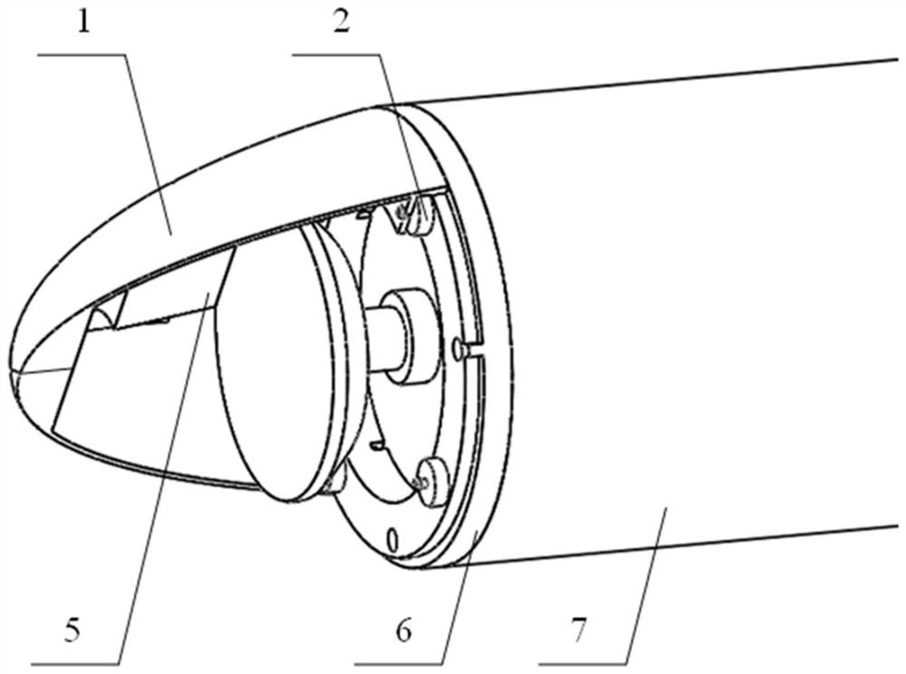
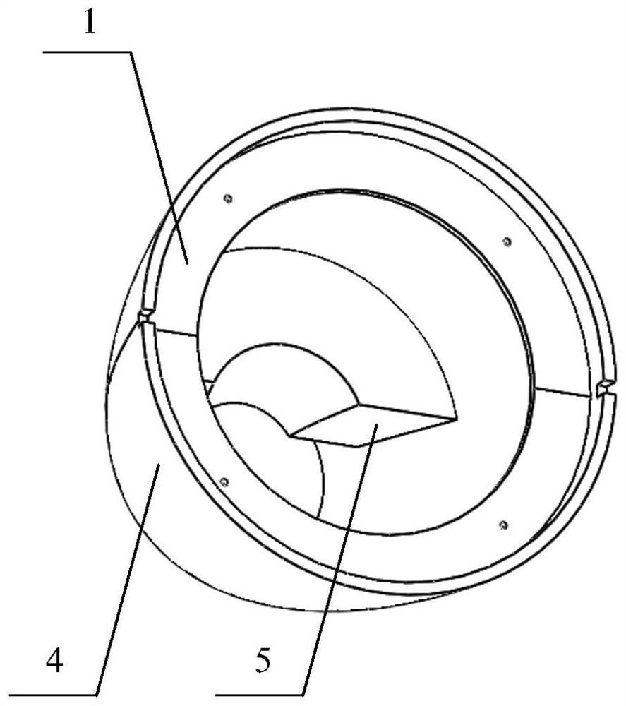
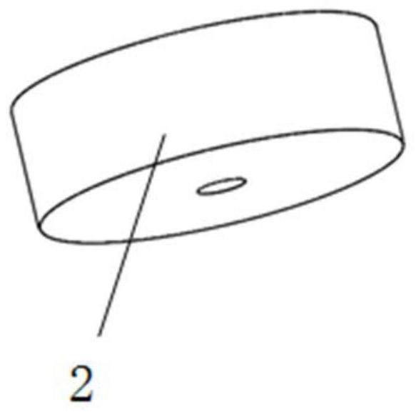
[0020] like Figure 1 to Figure 6 As shown, the present invention provides a detachable bow structure of a supercavitating underwater vehicle, including a split-type shroud unit, a de-energized electromagnet unit, a connecting rib ring and a vehicle hull; a split-type guide The shroud unit is composed of the upper part 1 of the shroud, the lower part 4 of the shroud and the buoyancy foam 5; the inner rib ring of the upper part 1 of the shroud and the lower part 4 of the shroud are reserved with four threaded holes evenly distributed in the circumferential direction and The angle between the threaded hole and the dividing line between the upper part 1 of the shroud and the lower p...


PUM


Abstract

The invention discloses a separable bow structure of a supercavitation underwater vehicle. The separable bow structure comprises a split type flow guide cover unit, a power-losing type electromagnet unit, a connecting rib ring and an underwater vehicle hull. The split type flow guide cover unit is composed of a flow guide cover upper portion, a flow guide cover lower portion and buoyancy foam, andthe buoyancy foam is fixed to an inner surface of the flow guide cover upper portion in a bonding mode. The power-losing electromagnet unit is composed of a ferromagnetic disc and a power-losing electromagnet. The ferromagnetic disc is fixed on an internal rib ring of the split type flow guide cover unit; the four ferromagnetic discs are evenly distributed in a circumferential direction, an included angle between the center of each ferromagnetic disc and a boundary between the upper portion of the flow guide cover and the lower portion of the flow guide cover is kept to be 45 degrees, circular grooves are evenly formed in the connecting rib ring in the circumferential direction, and power-losing type electromagnets are installed in the circular grooves; a connecting rib ring is in threaded connection with the underwater vehicle hull; and a power line channel is further formed in the circular grooves and used for connecting the power-losing type electromagnets with a power supply unitin the underwater vehicle hull through a power line.

Description

technical field [0001] The invention relates to the field of supercavitation underwater vehicles, in particular to a bow design method suitable for supercavitation underwater vehicles. Background technique [0002] As a new concept underwater vehicle, supercavitating underwater vehicle is essentially different from the traditional vehicle in terms of hydrodynamic principle. Using supercavitation technology can generate a cavitation bubble that completely surrounds the vehicle, so that the vehicle is isolated from water, similar to moving in the air, and the drag reduction can even reach 90%. At present, the two main factors restricting the development of supercavitation vehicles are the stability control of supercavitation and energy problems. It is one of the future development directions to develop an underwater vehicle that can not only conduct conventional non-supercavitating underwater navigation but also have the capability of supercavitating underwater navigation. ...

Claims


Application Information

Patent Timeline
Patent Type & Authority Applications(China)
IPC IPC(8): B63B1/38B63B3/46
CPCB63B1/38B63B3/46B63B2001/382Y02T70/10
Inventor 王树新杨绍琼王延辉陈光耀牛文栋马伟
Owner TIANJIN UNIV
Why Eureka
Try Eureka