Airship detection load layout structure

A technology for detecting loads and layout structures, applied in the field of detection, which can solve the problems of limited detection range and distance of moving targets, limited detection range and detection distance, etc.

Pending Publication Date: 2020-10-27
湖南航天远望科技有限公司
View PDF2 Cites 1 Cited by
  • Summary
  • Abstract
  • Description
  • Claims
  • Application Information

AI Technical Summary

Problems solved by technology

[0006] In addition, the detection load is installed under the airship, and the detection direction is downward, so the detection range and detection distance are limited, especially for moving targets.

Method used


Image

  • Airship detection load layout structure
  • Airship detection load layout structure
  • Airship detection load layout structure

Examples


Embodiment 1

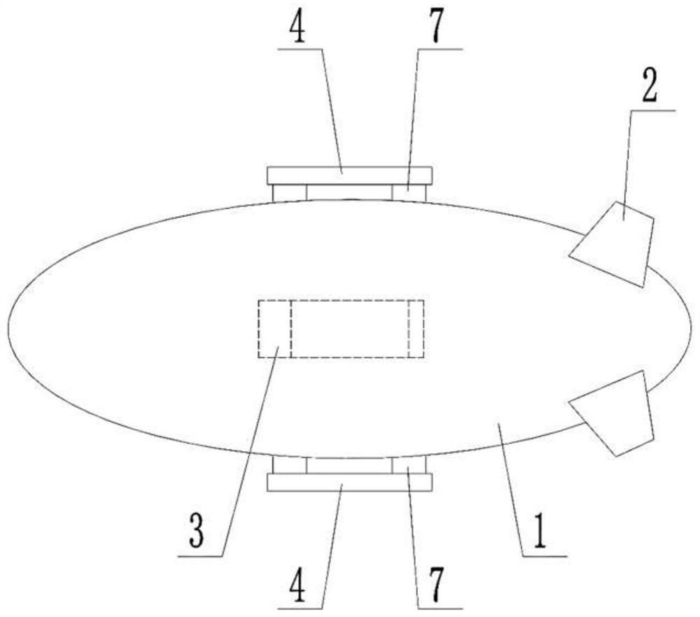
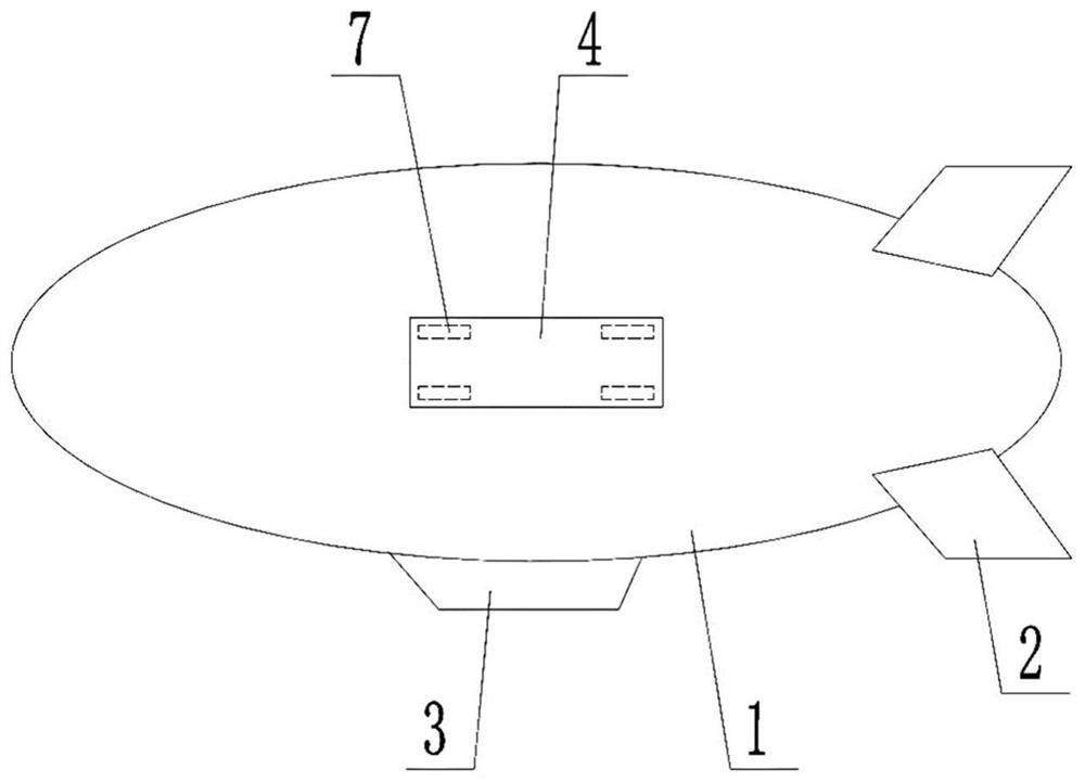
[0027] see Figure 1-2 , the airship detection load layout structure of the present embodiment is mainly composed of airship capsule 1, empennage 2, pod 3, detection load 4, counterweight device 5, pneumatic rectification device 6, skin support 61, skin 62, mounting frame 7 composed of:

[0028] see Figure 1-2 , the airship capsule 1 is a soft capsule; the empennage 2 is installed at the tail of the airship capsule, which is an "X" or "ten" empennage; the pod 3 is installed at the bottom of the airship capsule 1, which is a general hanger Cabin structure; the detection load 4 is a measuring device, which is installed in combination with the airship capsule 1 through the mounting frame 7, and the mounting frame 7 adopts a light-weight and high-strength structure. The detection load 4 is installed on both sides of the flying capsule body 1 and has a symmetrical installation structure. Both sides of the airship capsule 1 are equipped with the detection load 4, and only the in...

Embodiment 2

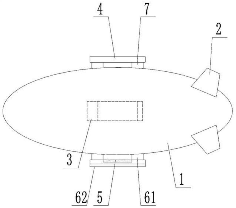
[0032] see Figure 3-4 The difference between this embodiment and Embodiment 1 is that the airship capsule body 1 is equipped with a detection load 4 on one side. The other side of the capsule body 1 is installed with a counterweight device 5 for weight balancing and a pneumatic rectification device 6 for pneumatic rectification compensation. The symmetry and consistency of the load weight and aerodynamic shape on both sides of the airship can be realized. This implementation method can eliminate the disadvantages of large airflow impact, poor stability, and poor operability caused by the load on one side to the greatest extent. Symmetrical installation can make full use of the airship. The body symmetry feature makes the aerodynamic performance of the whole system less affected and the measurement stability is better. On the one hand, it can maintain the consistency of weight distribution on both sides of the airship platform; on the other hand, the simulation analysis shows...


PUM


Abstract

The invention discloses an airship detection load layout structure, which comprises an airship bag body, an empennage arranged at the tail of the airship bag body and a nacelle arranged at the bottomof the airship bag body, wherein detection loads are arranged on one side or two sides of the airship bag body. The detection load is installed on the side face of the airship to track and detect a moving target in the air, the laying area is large, the target tracking capacity is high, the radar detection distance can be remarkably increased, and the measurement range and the environmental adaptability of airship-borne detection equipment are improved. The detection load is arranged on the side surface. The airship is flexible to take off and land and convenient to maintain.

Description

technical field [0001] The invention belongs to the field of detection, and in particular relates to an airship detection load layout structure. Background technique [0002] From the 1930s to the 1940s, the world's first set of equipment capable of receiving electromagnetic waves and the first radar system were successfully developed. The most notable features of this set of radars are the multiple towers and the transmitting and receiving antennas hung between them. . During World War II, the ground-based radar chain deployed by the British Air Force provided important guidance information for its own interceptors in response to German air attacks; In recent years, with the development of electronic technology, radar measurement has gradually shifted from air-air interceptors to air-sea early warning detection and ship anti-submarine. Stable and reliable measurement data are required for early warning detection, maritime moving target measurement and anti-submarine. How...

Claims


Application Information

Patent Timeline
Patent Type & Authority Applications(China)
IPC IPC(8): B64B1/06B64B1/38
CPCB64B1/06B64B1/38
Inventor 王俊黄少坡肖红立侯文杰
Owner 湖南航天远望科技有限公司
Why Eureka
Try Eureka