Lifting control device for electric clothes hanger

A lifting control and drying rack technology, applied in the field of clothes drying racks, can solve the problems of limited output torque, affecting the output torque, etc., and achieve the effects of simple adjustment and maintenance, stable transmission, and small footprint

Active Publication Date: 2022-03-15
GUANGZHOU NOVO SUN SHADING TECHN
View PDF11 Cites 0 Cited by
  • Summary
  • Abstract
  • Description
  • Claims
  • Application Information

AI Technical Summary

Problems solved by technology

The use of a small motor can reduce the volume and make the overall structure thinner, but the output torque of the small motor is limited, which will affect the size of the output torque; and thinner also requires the rope wheel to be as thin as possible, such as ensuring the length of the clothesline to be stored To meet the requirements, the diameter of the rope winding wheel must be increased. The miniaturization of the motor and the increase in the diameter of the rope winding wheel will lead to the size of the output torque and the spatial structure layout

Method used


Image

  • Lifting control device for electric clothes hanger
  • Lifting control device for electric clothes hanger
  • Lifting control device for electric clothes hanger

Examples


Embodiment Construction

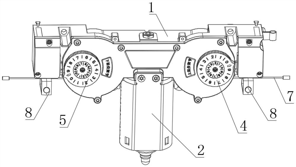
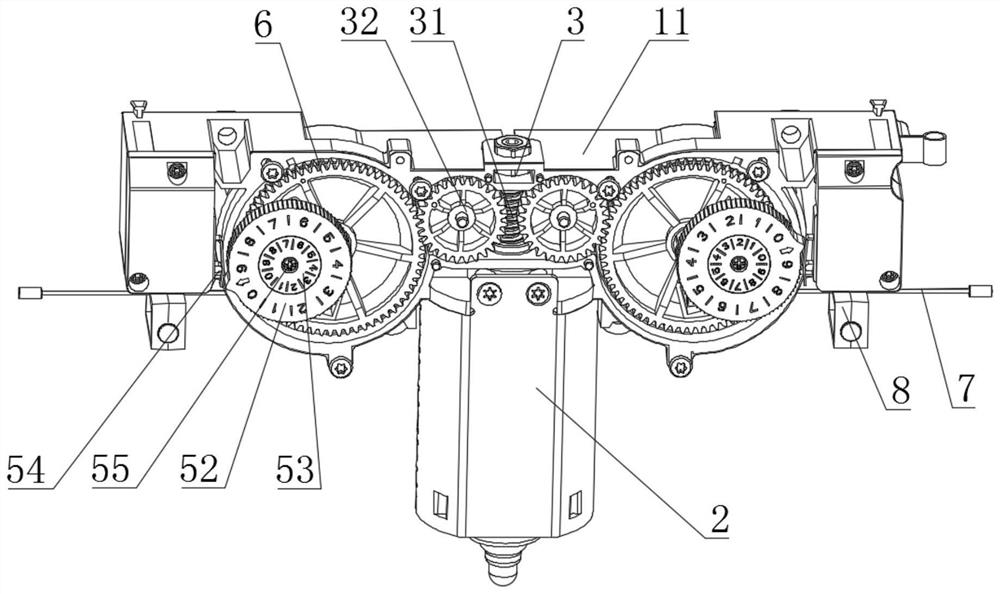
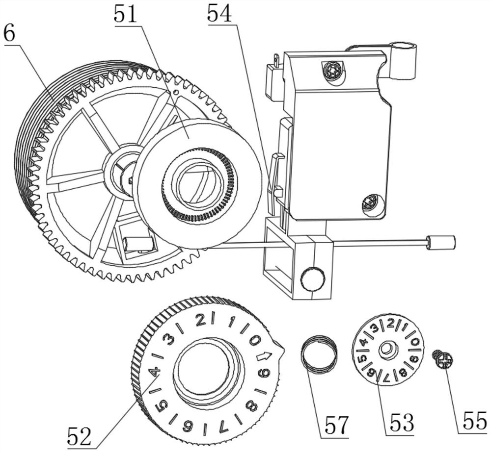
[0040] A lifting control device for an electric drying rack, such as figure 1 , figure 2 As shown, it includes a motor 2, a housing 1, a transmission mechanism 3, a rope reel 6, a clothesline 7, an upper limit control mechanism 4, a lower limit control mechanism 5 and an emergency stop control mechanism 8. In this embodiment, the housing 1 is composed of front and rear shells (front shell 12 and rear shell 11), the transmission mechanism 3 and the rope winding wheel 6 are installed inside the shell 1, and the upper limit control mechanism 4 and the lower limit control mechanism 5 are installed in the shell Body 1 outside, convenient to adjust at any time.

[0041] The transmission mechanism 3 includes a worm 31 and a first transmission gear 32, the worm 31 is in transmission connection with the output end of the motor 2, the first transmission gear 32 of the two groups is respectively in transmission connection with the worm 31, the two groups of The rope winding wheels 6 a...


PUM


Abstract

A lifting control device for an electric clothes hanger, comprising a motor, a transmission mechanism, a rope winding wheel, an upper limit control mechanism and a lower limit control mechanism, the transmission mechanism includes a worm and a first transmission gear, the diameter of the first transmission gear is smaller than the rope winding wheel, Both the upper and lower limit control mechanisms include a first contact switch, a pinion, a transmission wheel, an adjustment wheel, a fixed plate and a spring. The meshing of the adjustment wheel drives the rotation of the adjustment wheel, and the protrusion of the adjustment wheel controls the motor to stop; the rope winding part is provided with an engaging structure including a through hole and a slot, the through hole is arranged radially, and the slot extends circumferentially to match the winding slot. catch. The present invention can use a motor with a smaller size to achieve a larger torque output, and can increase the diameter of the rope winding wheel and reduce the thickness, making the overall device lighter and smaller; the limit control mechanism is simple and compact in structure, easy to install and Easy to adjust; clothesline installation and replacement is simple and convenient.

Description

technical field [0001] The invention relates to the technical field of clothes drying racks, in particular to a lifting control device for electric clothes drying racks. Background technique [0002] Electric clothes drying racks are widely used because they can be lifted and lowered automatically and are easy to use. One end of the clothesline of the electric clothes rack is connected to the clothesline, the clothes are hung on the clothesline, and the other end of the clothesline is connected to the lifting control device, and the lifting control device controls the lifting of the clothesline, so that the clothesline up or down. The lifting control device generally includes a motor and a rope winding wheel. The clothesline is wound on the rope winding wheel. The motor is connected to the rope winding wheel to drive the rope winding wheel to rotate. During the lifting process, the lifting stroke of the clothesline needs to be controlled. Stop descending when reaching the ...

Claims


Application Information

Patent Timeline
Patent Type & Authority Patents(China)
IPC IPC(8): B66D1/12B66D1/14B66D1/28B66D1/34B66D1/46B66D1/54B66D1/56B66D1/60D06F57/12H02K7/116
CPCB66D1/12B66D1/14B66D1/28B66D1/34B66D1/46B66D1/54B66D1/56B66D1/60H02K7/1166D06F57/125
Inventor 欧欢庆
Owner GUANGZHOU NOVO SUN SHADING TECHN
Why Eureka
Try Eureka