Jaw electromagnetic clutch clamping device

An electromagnetic clutch and jaw-type technology, applied in the direction of magnetic drive clutches, clutches, non-mechanical drive clutches, etc.

Active Publication Date: 2020-10-27
湖州忻宝自动化科技有限公司
View PDF4 Cites 2 Cited by
  • Summary
  • Abstract
  • Description
  • Claims
  • Application Information

AI Technical Summary

Problems solved by technology

[0004] Aiming at the deficiencies in the use of the existing jaw electromagnetic clutch proposed in the background technology, the present invention provides a clamping device for ja

Method used


Image

  • Jaw electromagnetic clutch clamping device
  • Jaw electromagnetic clutch clamping device
  • Jaw electromagnetic clutch clamping device

Examples


Example Embodiment

[0015] The technical solutions in the embodiments of the present invention will be clearly and completely described below in conjunction with the accompanying drawings in the embodiments of the present invention. Obviously, the described embodiments are only a part of the embodiments of the present invention, rather than all the embodiments. Based on the embodiments of the present invention, all other embodiments obtained by those of ordinary skill in the art without creative work shall fall within the protection scope of the present invention.
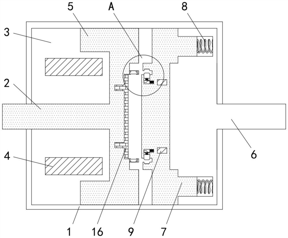
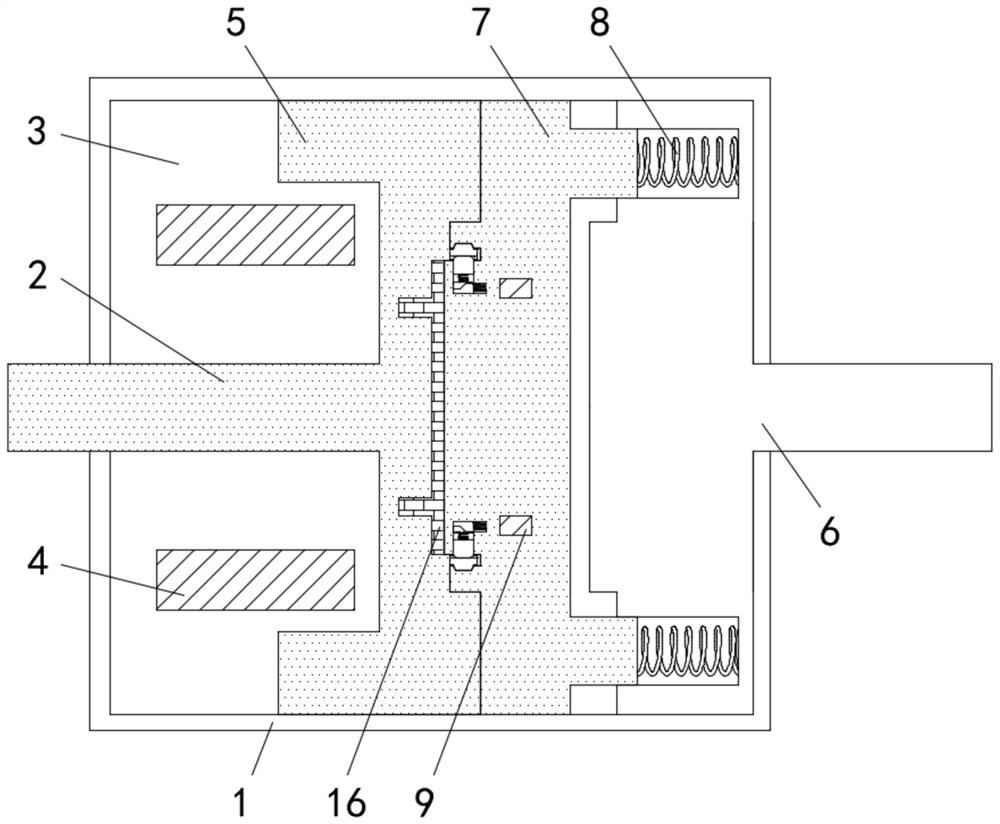
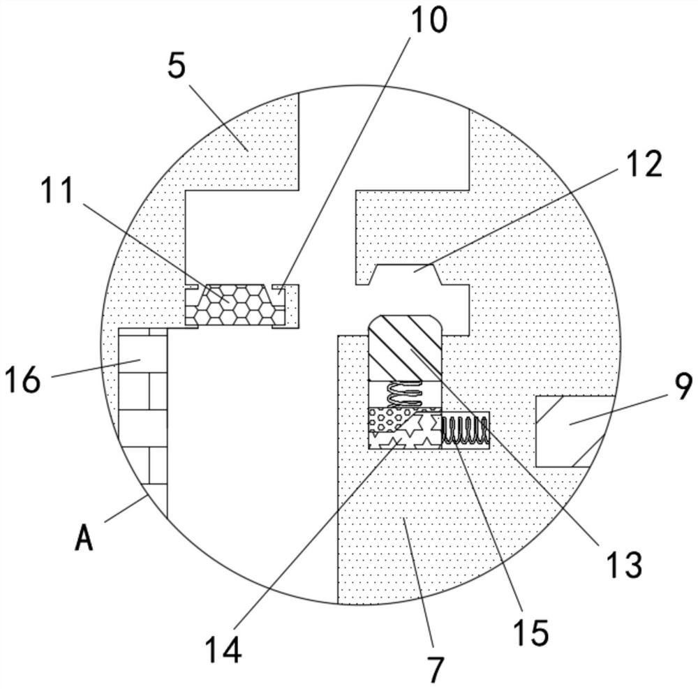
[0016] See Figure 1-3 , A jaw type electromagnetic clutch clamping device, comprising a casing 1, one end of the inner cavity of the casing 1 is movably connected with a driving shaft 2, and the inner cavity of the casing 1 is fixedly connected with the outer surface of the driving shaft 2 The yoke 3, the middle of the inner cavity of the yoke 3 is fixedly installed with the coil I4, one end of the driving shaft 2 is fixedly connected t...


PUM


Abstract

The invention relates to the technical field of mechanical equipment and discloses a jaw electromagnetic clutch clamping device which comprises a case; a driving shaft is movably connected with one end of the cavity of the case; a magnet yoke movably connected with the external surface of the driving shaft is fixedly connected with the cavity of the case; and a first coil is fixedly mounted in themiddle of the cavity of the magnet yoke. Through a novel clamping structure, the first coil generates magnetic force after being electrified to repel a magnetic patch outwards and attracts a driven disc towards a driving disc, so that one end of the magnetic patch is in contact with one end of the driven disc to generate friction; the driving disc is clamped with one end of the magnetic patch, sothat the magnetic patch and the driving shaft rotate synchronously; through friction generated by the magnetic patch and the driven disc, the driven disc drives a driven shaft to rotate; and in addition, along with increase of current in the first coil, the friction between the magnetic patch and the driven disc is increased, so that the rotary speed of the driven shaft is increased, and rotary speed difference between the driving shaft and the driven shaft is reduced to enable a fixture block and a movable cavity to be clamped more easily.

Description

technical field [0001] The invention relates to the technical field of mechanical equipment, in particular to a clamping device of a jaw type electromagnetic clutch. Background technique [0002] A clutch is a device similar to a switch that engages or disengages power transmission. The active part and the driven part of the clutch mechanism can be temporarily separated and gradually engaged, and it is possible to rotate relatively during the transmission process. Traditional clutches It is divided into four types: electromagnetic clutch, magnetic powder clutch, friction clutch and hydraulic clutch. [0003] The electromagnetic clutch is an electromagnetic machine that uses the principle of electromagnetic induction and the friction between the inner and outer friction plates to make the two rotating parts in the mechanical transmission system, and the driven part can be combined with or separated from the active part without stopping the rotation. Connectors, traditional e...

Claims


Application Information

Patent Timeline
IPC IPC(8): F16D27/04F16D27/09F16D27/14
CPCF16D27/04F16D27/09F16D27/14F16D2027/008
Inventor 王旭
Owner 湖州忻宝自动化科技有限公司
Why Eureka
Try Eureka