Magnetic isolation device of magnetic encoder

A magnetic encoder and encoder technology, applied in the field of magnetic isolation devices, can solve the problems of high-demand installation process, increased motor manufacturing cost, and increased overall length of the motor.

Pending Publication Date: 2020-10-27
SHANGHAI ANPU MINGZHI AUTOMATION EQUIP
View PDF0 Cites 0 Cited by
  • Summary
  • Abstract
  • Description
  • Claims
  • Application Information

AI Technical Summary

Problems solved by technology

One of the existing solutions is to increase the length of the rear shaft of the motor through design to ensure that the magnetic field strength of the rotor is small enough on the encoder side, but this method will increase the overall length of the motor
The second solution is to reduce the distance between the magnetic steel of the magnetic encoder and the magnetic sensor chip to increase the sampling of effective signals, but this requires a more demanding installation process
[0003] The two existing solutions will increase the manufacturing cost of the motor and cannot effectively isolate the magnetic encoder

Method used


Image

  • Magnetic isolation device of magnetic encoder
  • Magnetic isolation device of magnetic encoder

Examples


Embodiment

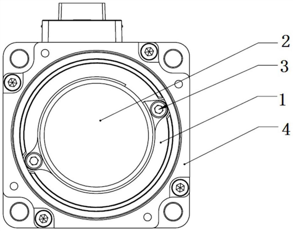
[0026] Such as figure 1 As shown, a magnetic isolation device of a magnetic encoder includes a magnetic isolation structure installed between the magnetic encoder body and the motor body; the magnetic encoder body is connected to the motor body; the magnetic isolation structure is installed on the The rear end cover of the motor body; the magnetic encoder body is located in the magnetic isolation structure.

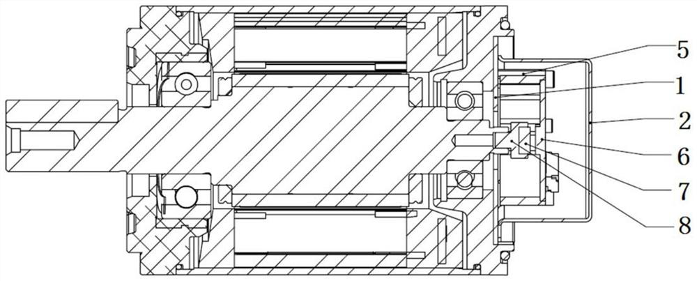
[0027] The magnetic isolation structure includes a magnetic isolation plate 1 and a protective cover 2. The magnetic isolation plate 1 is used to isolate the magnetic encoder body and the motor body to isolate the magnetic field interference from the motor; the protective cover 2 is used to form a shielding space to isolate the external magnetic field interference.

[0028] The magnetic isolation structure is fixedly connected to the rear end cover 4 of the motor body through screws 3 . The magnetic isolation plate 1 and the protective cover 2 are connected together by ...


PUM


Abstract

The invention relates to a magnetic isolation device of a magnetic encoder. The magnetic isolation device is installed between a magnetic encoder body and a motor body, the magnetic encoder body is connected with the motor body, the magnetic isolation device comprises a magnetic isolation structure, the magnetic isolation structure is installed on a rear end cover (4) of the motor body, and the magnetic encoder body is located in the magnetic isolation structure. The encoder body and the motor body are isolated by the magnetic isolation structure, and magnetic field interference from the motorbody is isolated. Compared with the prior art, the magnetic isolation device has the advantages of good magnetic isolation effect, low manufacturing cost, simple structure, convenience in installation and the like.

Description

technical field [0001] The invention relates to the technical field of magnetic encoders, in particular to a magnetic isolation device for a magnetic encoder. Background technique [0002] External magnetic fields, such as rotor magnets, motor rear-end brakes, strong magnetic environments, etc., will interfere with the magnetic encoder, and in severe cases will cause the failure of the motor control. In the past, the magnetic encoder was directly installed at the end of the motor without magnetic shielding, and the external magnetic field would interfere with the encoder. One of the existing solutions is to increase the length of the rear shaft of the motor through design to ensure that the magnetic field strength of the rotor is small enough on the encoder side, but this method will increase the overall length of the motor. The second solution is to reduce the distance between the magnetic steel of the magnetic encoder and the magnetic sensor chip to increase the sampling ...

Claims


Application Information

Patent Timeline
Patent Type & Authority Applications(China)
IPC IPC(8): G01D5/244
CPCG01D5/244
Inventor 赵鹏陈文君高宏伟
Owner SHANGHAI ANPU MINGZHI AUTOMATION EQUIP
Why Eureka
Try Eureka