Photoelectric coupling device

A photoelectric coupling and light source technology, applied in the coupling of optical waveguides, optics, light guides, etc., can solve problems such as difficult to meet requirements and low upper limit of operating frequency

Inactive Publication Date: 2020-10-27
NINGBO QUNXIN MICRO-ELECTRONICS CO LTD
View PDF5 Cites 0 Cited by
  • Summary
  • Abstract
  • Description
  • Claims
  • Application Information

AI Technical Summary

Problems solved by technology

[0005] However, the existing infrared-based optocoupler devices have the problem of a low upper limit of operating frequency. As the i...

Method used


Image

  • Photoelectric coupling device
  • Photoelectric coupling device
  • Photoelectric coupling device

Examples


Embodiment Construction

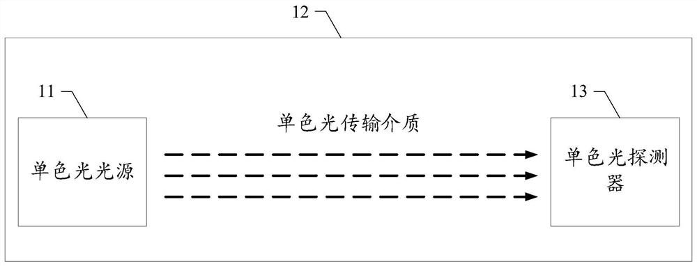
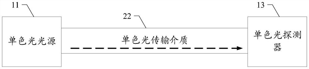
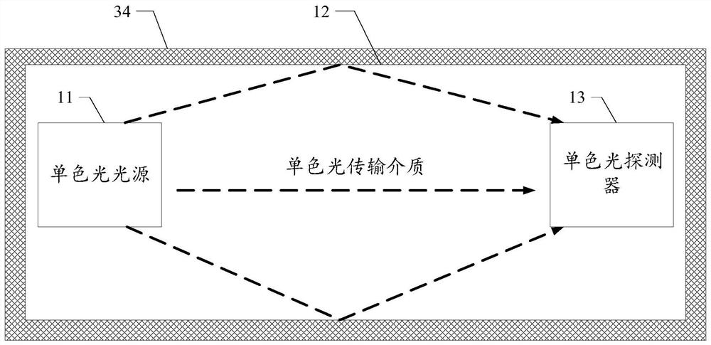
[0037] As mentioned above, the existing photocoupler generally consists of three parts: a light source for emitting light, an optical transmission medium, and a light receiving and signal amplifying device. In the prior art, infrared rays are generally used as the medium carrier for signal transmission, infrared light sources are used to emit infrared rays, and infrared detectors are used to receive and convert them into electrical signals at the output end. However, existing infrared-based optocoupler devices are increasingly difficult to meet the demand.

[0038] The inventors of the present invention have found through research that in the prior art, photoelectric coupling devices based on infrared rays are limited by conditions such as materials and processes. At present, the upper limit of the operating frequency is 50Mhz, and there is a problem that the upper limit of the operating frequency is lower. The Internet and the like require faster and faster data transmission ...


PUM


Abstract

The invention provides a photoelectric coupling device, which may include: a monochromatic light source for emitting monochromatic light; a monochromatic light detector used for receiving the monochromatic light; and a monochromatic light transmission medium, wherein at least one part of the monochromatic light transmission medium is located between the monochromatic light source and the monochromatic light detector, and the monochromatic light transmission medium is used for transmitting monochromatic light to the monochromatic light detector through the monochromatic light transmission medium, wherein the wavelength of the monochromatic light is smaller than that of the infrared rays. According to the invention, the upper limit of the working frequency of the photoelectric coupling device can be improved, and the user requirements can be better met.

Description

technical field [0001] The invention relates to the field of photoelectric technology, in particular to a photoelectric coupling device. Background technique [0002] A photocoupler uses light as a medium to transmit electrical signals. It has a good isolation effect on input and output electrical signals, so it is widely used in various circuits. At present, it has become one of the most diverse and widely used optoelectronic devices. [0003] Existing optocoupler devices generally consist of three parts: a light source for emitting light, an optical transmission medium, and light receiving and signal amplifying devices. The input electrical signal is converted into an optical signal, so that the light source emits light of a certain wavelength, which is received by the photodetector to generate a photocurrent, which is further amplified and output, thereby completing the conversion of electricity-optical-electricity, which plays a role The role of input, output, and iso...

Claims


Application Information

Patent Timeline
IPC IPC(8): G02B6/42
CPCG02B6/4286G02B6/4296G02B6/4201G02B2006/12104G02B2006/12123G02B2006/12035G02B6/4202H04B10/25H04B10/27
Inventor 晁阳
Owner NINGBO QUNXIN MICRO-ELECTRONICS CO LTD
Why Eureka
Try Eureka