
Clock data recovery circuit

A clock data recovery, circuit technology, applied in the direction of electrical components, automatic power control, etc., can solve the problems of IC chips with many pins and high manufacturing costs

Pending Publication Date: 2020-10-27
牛芯半导体(深圳)有限公司
View PDF0 Cites 0 Cited by
  • Summary
  • Abstract
  • Description
  • Claims
  • Application Information

AI Technical Summary

Problems solved by technology

[0004] The purpose of this application is to provide a clock data recovery circuit to solve the technical problems in the prior art that the clock reference source needs to be provided through an off-chip structure, resulting in more pins of the IC chip and high manufacturing costs

Method used


Image

  • Clock data recovery circuit
  • Clock data recovery circuit
  • Clock data recovery circuit

Examples


Embodiment Construction

[0024] Typical implementations embodying the features and advantages of the present application will be described in detail in the following description. It should be understood that the present application can have various changes in different embodiments without departing from the scope of the present application, and that the descriptions and illustrations therein are illustrative in nature and not limiting this application.

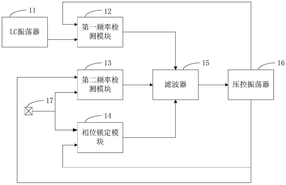
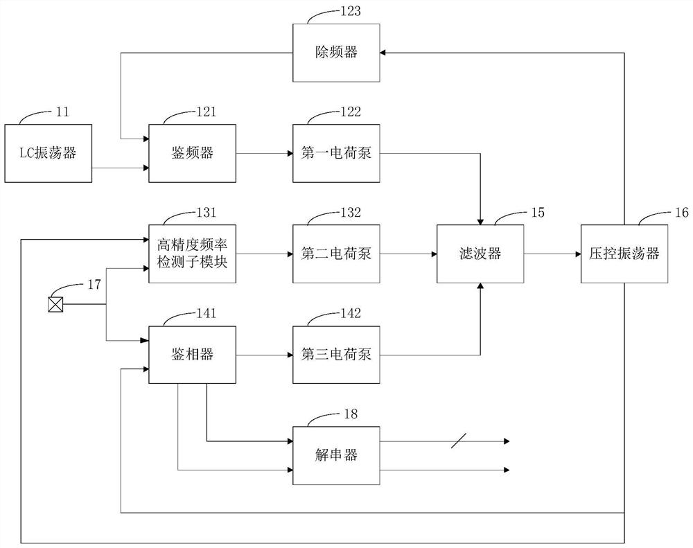
[0025] refer to figure 1 , figure 1 It is a block diagram of a clock data recovery circuit in an embodiment of the present application. The clock data recovery circuit in this embodiment is generally applied to an IC chip in a serial communication system. The clock data recovery circuit in this embodiment may include an LC An oscillator 11 , a first frequency detection module 12 , a second frequency detection module 13 , a phase locking module 14 , a filter 15 and a voltage-controlled oscillator 16 .

[0026] The first frequency detection module 12...


PUM


Abstract

The present application relates to a clock data recovery circuit and a loop adjustment method, the clock data recovery circuit comprising: an LC oscillator for outputting a signal of a predetermined frequency; a first frequency detection module which comprises two input ends, the first frequency detection module is used for outputting driving current according to the frequency difference between signals input by the two input ends, and one input end of the first frequency detection module is connected with the output end of the LC oscillator; and a second frequency detection module, wherein the second frequency detection module comprises a clock input end and a data input end, and is used for outputting a driving current according to a frequency difference between a signal input by the clock input end of the second frequency detection module and a signal input by the data input end of the second frequency detection module. According to the technical scheme provided by the invention, pins of the IC chip can be effectively reduced, and the manufacturing cost of the IC chip is reduced.

Description

technical field [0001] The present application relates to the technical field of integrated circuits, in particular to a clock data recovery circuit. Background technique [0002] In the serial communication system, the clock data recovery circuit plays a key role in the receiving IC chip, and the receiving IC chip extracts the clock from the input serial data through the clock data recovery circuit and performs data recovery. [0003] The premise of data recovery is to ensure that the input serial data is synchronized with the internal clock of the IC chip. In related technologies, the clock data recovery circuit design of the IC chip generally uses an off-chip structure to provide a clock reference source, such as an off-chip crystal The oscillator is used to provide the reference clock. Since the reference clock needs to be provided through an off-chip structure, the pins of the IC chip will be more, and the manufacturing cost of the IC chip will be higher. Contents of ...

Claims


Application Information

Patent Timeline
Patent Type & Authority Applications(China)
IPC IPC(8): H03L7/087H03L7/08H03L7/099
CPCH03L7/087H03L7/0807H03L7/0998Y02D10/00
Inventor 唐重林刘寅
Owner 牛芯半导体(深圳)有限公司
Learn More