Beancurd skin skewering device
A technology for bean skin and storage, which is applied in the field of string insertion devices for bean skin
- Summary
- Abstract
- Description
- Claims
- Application Information
AI Technical Summary
Problems solved by technology
Method used
Image

Examples
Embodiment 1
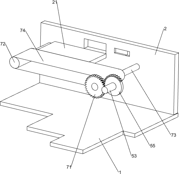
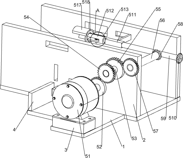
[0025] A kind of string inserting device for bean curd, such as Figure 1-5 As shown, it includes a base plate 1, a mounting plate 2, a support plate 21, a storage block 3, a storage plate 4, a curling mechanism 5 and a label insertion mechanism 6, and the front side of the top of the base plate 1 is connected with a storage block 3, and the left rear of the storage block 3 The top of the bottom plate 1 is connected with a storage plate 4, and the top of the bottom plate 1 on the rear side of the storage plate 4 is connected with two mounting plates 2, the two mounting plates 2 are symmetrical front and rear, and the left side of the front side of the rear mounting plate 2 is connected with a support plate 21 , a curling mechanism 5 is provided between the support plate 21, the mounting plate 2 and the storage block 3, and a label insertion mechanism 6 is provided between the bottom plate 1, the front mounting plate 2 and the storage panel 4, and the transmission of the label i...
Embodiment 2
[0030] On the basis of Example 1, such as Figure 6 As shown, a transport mechanism 7 is also included, and the transport mechanism 7 includes a fifth gear 71, a roller 72, a seventh transmission rod 73 and a conveyor belt 74, and two seventh transmission rods are rotationally connected between the two mounting plates 2 73. A roller 72 is connected to the seventh transmission rod 73, a conveyor belt 74 is connected between the two rollers 72, and a fifth gear 71 is connected to the front end of the seventh transmission rod 73 on the right side, and the fifth gear 71 and the second half gear 55 engaged.
[0031] A plurality of bean curds can be placed on the conveyor belt 74, and half of the bean curds are positioned on the support plate 21. The counterclockwise rotation of the first transmission rod 53 drives the second half gear 55 to rotate counterclockwise. The counterclockwise rotation of the second half gear 55 meshes with the fifth gear 71 first, and the counterclockwis...
Embodiment 3
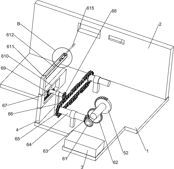
[0033] On the basis of Example 2, such as Figure 7 As shown, it also includes a forward and backward mechanism 8, and the forward and backward mechanism 8 includes an eighth transmission rod 81, a first belt transmission group 82, a missing tooth gear 83, a ninth transmission rod 84, a sixth gear 85, and a second belt transmission group 87 , the fourth bevel gear 88, the missing tooth bevel gear 89 and the second rack 810, the rear side of the front side mounting plate 2 is rotatably connected with the eighth transmission rod 81, the eighth transmission rod 81 and the seventh transmission rod 73 on the right side The first belt transmission group 82 is connected between them, the eighth transmission rod 81 is connected with a toothless gear 83, the middle part of the front side of the rear mounting plate 2 is rotatably connected with a ninth transmission rod 84, and the front end of the ninth transmission rod 84 is connected to The sixth gear 85 is arranged, the sixth gear 85...
PUM
 Abstract
Description
Claims
Application Information
 - R&D
- Intellectual Property
- Life Sciences
- Materials
- Tech Scout
- Unparalleled Data Quality
- Higher Quality Content
- 60% Fewer Hallucinations
Browse by: Latest US Patents, China's latest patents, Technical Efficacy Thesaurus, Application Domain, Technology Topic, Popular Technical Reports.
© 2025 PatSnap. All rights reserved.Legal|Privacy policy|Modern Slavery Act Transparency Statement|Sitemap|About US| Contact US: help@patsnap.com