Switch middle plate stamping continuous die

A technology of switches and dies, applied in metal processing equipment, forming tools, manufacturing tools, etc., can solve the problems of affecting the processing accuracy of other stations, the involvement of the middle plate and the waste belt, and increasing production costs, so as to improve production quality and Machining accuracy, small size, guarantee neat effect

Inactive Publication Date: 2020-10-30
温州创睿五金模具有限公司
View PDF7 Cites 1 Cited by
  • Summary
  • Abstract
  • Description
  • Claims
  • Application Information

AI Technical Summary

Problems solved by technology

[0004] The existing switch middle plate is stamped and formed by stamping continuous die. When the existing stamping continuous die is processing the middle plate, the middle plate is stamped and formed in the middle area of ​​the material belt, and the formed middle plate and the waste belt are formed. In the last step, the connection point between the two is cut off to form a separate middle plate part, and this stamping method will form redundant strip edges on both sides of the strip along its length, and because It is in the last step that the cutting between the middle plate and the scrap belt is realized. When the middle plate and the scrap belt are processed in the previous stamping stations, there will be dragging between the middle plate and the waste belt. When one of the processing workers When there is a deviation in the accuracy of one station, it will affect the processing accuracy of other stations, resulting in low processing accuracy and low utilization rate of the existing stamping continuous die, which increases the production cost of the product

Method used


Image

  • Switch middle plate stamping continuous die
  • Switch middle plate stamping continuous die
  • Switch middle plate stamping continuous die

Examples


Embodiment Construction

[0030] The present invention will be described in further detail below in conjunction with the accompanying drawings.

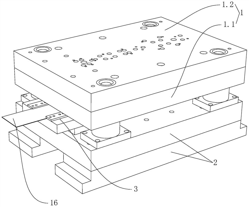
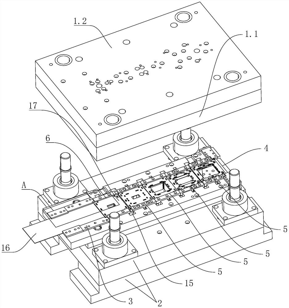
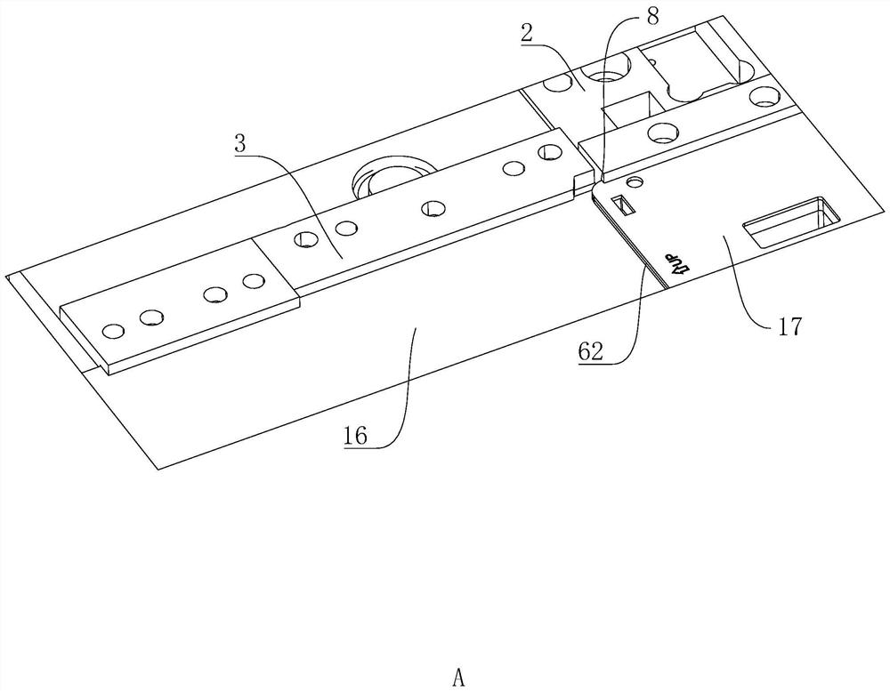
[0031] refer to Figure 1 to Figure 8 , a switch mid-plate stamping continuous die, including an upper die 1 and a lower die 2, the upper die 1 includes a main positioning plate 1.1 and a guide plate 1.2 arranged on the side of the main positioning plate 1.1 facing away from the lower die 2. Between the main positioning plate 1.1 and the lower die 2, there are a feed channel 3 and a discharge port 4, and between the main positioning plate 1.1 and the lower die 2, there are a plurality of processes arranged in sequence from the feed channel 3 to the discharge port 4. Station 5. The width of the feed channel 3 is the same as that of the middle plate, and the processing station 5 connected to the feed channel 3 is named as the first station 6 .

[0032] The first station 6 includes a punch 61 arranged on the main positioning plate 1.1 and a die 62 fixedly arra...


PUM


Abstract

The invention discloses a switch middle plate stamping continuous die. The switch middle plate stamping continuous die comprises an upper die and a lower die. A feed way and a discharge port are formed between the upper die and the lower die. Multiple machining stations sequentially arranged from the feed way to the discharge port are arranged between the upper die and the lower die. The width ofthe feed way and the width of a middle plate are equal. The machining station connected with the feed way is the first station. The first station comprises a male die and a female die. A die cavity isformed between the male die and the female die. A first material way communicating with the die cavity is formed between the male die and the female die. A cutter for cutting a material strip into ablock body is arranged at the position, above the feed way, of the upper die. An abutting knife for cutting the local contour of the periphery of the block body out is arranged on the side, opposite to the cutter, of the first station, of the upper die, and the abutting knife cooperates with the cutter to be used for cutting the overall periphery contour of the middle plate out on the block body.The switch middle plate stamping continuous die has the following beneficial effects that the utilization rate of the material strip is increased, the production cost of products is reduced, the die is smaller in overall size, better in rigidity and longer in service life, and a punch is more convenient to disassemble and assemble.

Description

technical field [0001] The invention relates to a die, in particular to a continuous die for punching a middle plate of a switch. Background technique [0002] The products and parts produced by the mold have high production efficiency, can realize high-speed mass production, save raw materials, and realize non-cutting processing; the product quality is stable and has good interchangeability; the operation is simple, and the operator does not have high technology advantages such as requirements. Among them, the stamping continuous die is more and more widely used. [0003] Stamping continuous die refers to the cold stamping die that uses strip-shaped stamping raw materials in one stamping stroke, and uses several different stations to complete multiple stamping processes at the same time on a pair of molds. The material belt moves once at a fixed distance until the product is completed. [0004] The existing switch middle plate is stamped and formed by stamping continuous...

Claims


Application Information

Patent Timeline
Patent Type & Authority Applications(China)
IPC IPC(8): B21D37/08B21D35/00
CPCB21D37/08B21D35/001
Inventor 王仁建
Owner 温州创睿五金模具有限公司
Why Eureka
Try Eureka