Steel bar welding device for building construction
A welding device and building construction technology, applied in the field of building construction, can solve the problems of lack of accurate and stable welding equipment, affect the scope of external tasks of the enterprise, and cannot meet special welding requirements, so as to improve construction quality, easy operation, and reduce labor costs. cost effect
- Summary
- Abstract
- Description
- Claims
- Application Information
AI Technical Summary
Problems solved by technology
Method used
Image

Examples
Embodiment 1
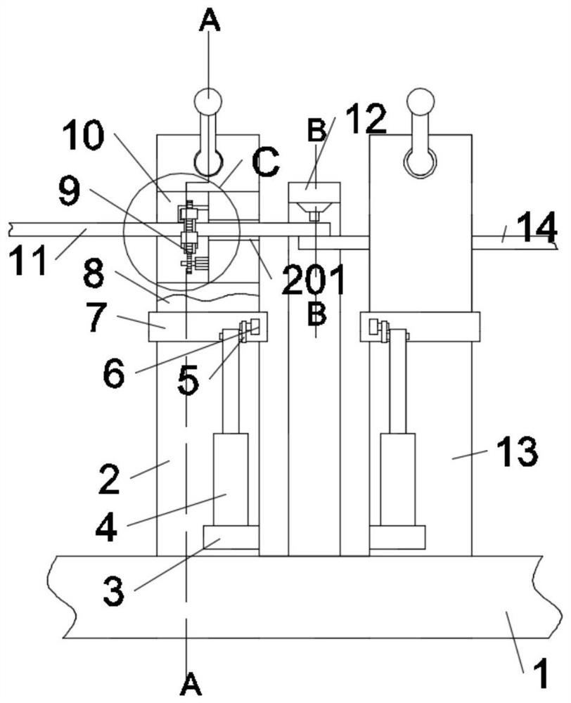
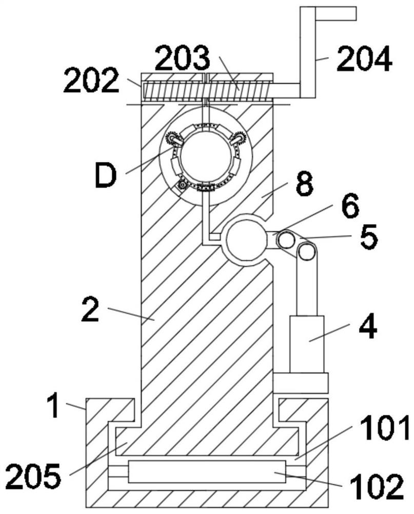
[0025] Such as figure 1 , figure 2 , image 3 , Figure 4 , Figure 5 , Figure 6 and Figure 7 As shown, in the embodiment of the present invention, a steel bar welding device for building construction includes a fixed base plate 1, and a left movable mounting seat 2 and a right movable mounting base 13 are connected to the fixed base plate 1. A first bracket 3 is fixed on the side of the left movable mounting seat 2, and a left telescopic rod 4 is fixed on the first bracket 3, and the upper end of the left telescopic rod 4 is hinged with a first rod 5, and the first rod 5 is hinged with a The second bracket 6, the second bracket 6 is fixed on the rotating shaft 7, the rotating shaft 7 is connected with a fitting block 8, and the fitting block 8 is fitted with the left movable mounting seat 2, and the fitting block 8 is connected with the left movable mounting seat 2. A semicircular groove 10 is relatively opened on the movable mounting seat 2, and a clamping screw-in ...
Embodiment 2
[0028] Such as figure 1 , figure 2 , Figure 4 , Figure 5 and Figure 6 As shown, in the embodiment of the present invention, the clamping and screwing device 9 includes a motor 901, the motor 901 is connected with a first gear 902, and the first gear 902 is meshed with a ring gear 903, and the ring gear 903 A number of evenly distributed arc-shaped sleeves 904 are placed on the top, and a second gear 905 and a third gear 906 are meshed on both sides of the upper half of the ring gear 903. The second gear 905 is connected to a first U-shaped rod 907, so The third gear 906 is connected with a second U-shaped bar 908, and the first U-shaped bar 907 and the second U-shaped bar 908 are fixed on the fitting block 8 at the bottom of the groove 10 and the left movable mounting seat 2. The motor 901 is fixed on the outer wall of the groove 10 .
[0029] In the embodiment of the present invention, step 2: then manually hold the shaking handle 204 and screw the screw 203 into the...
Embodiment 3
[0031] Such as Figure 6As shown, in the embodiment of the present invention, the outer ring of the ring gear 903 is provided with flat teeth 9031, the upper and lower end surfaces of the ring gear 903 are provided with a circle of evenly distributed bosses 9032, and the outer ring of the ring gear 903 is nested The arc-shaped sleeve 904 is made of rubber, and the inner ring of the arc-shaped sleeve 904 is provided with an internal thread 9041 , and the internal thread 9041 cooperates with the boss 9032 on the ring gear 903 .
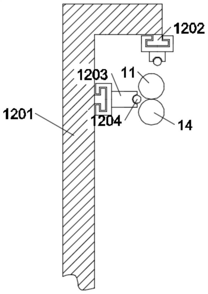
[0032] In an embodiment of the present invention, step 3: when the first steel bar 11 and the second steel bar 14 arrive at the specified position near the welding machine 1203, stop the motor 901, and now the welding machine 1203 can be used to move left and right on the T-shaped platform 1202 Come for high-precision welding.
PUM
 Abstract
Description
Claims
Application Information
 - Generate Ideas
- Intellectual Property
- Life Sciences
- Materials
- Tech Scout
- Unparalleled Data Quality
- Higher Quality Content
- 60% Fewer Hallucinations
Browse by: Latest US Patents, China's latest patents, Technical Efficacy Thesaurus, Application Domain, Technology Topic, Popular Technical Reports.
© 2025 PatSnap. All rights reserved.Legal|Privacy policy|Modern Slavery Act Transparency Statement|Sitemap|About US| Contact US: help@patsnap.com