Semi-automatic channeling machine

A grooving machine, semi-automatic technology, applied in turning equipment, auxiliary devices, manufacturing tools, etc., can solve problems such as unstable quality, different depths of product grooves, and slow production efficiency

Inactive Publication Date: 2020-10-30
FUZHOU ZHENXIE PIPE
View PDF7 Cites 0 Cited by
  • Summary
  • Abstract
  • Description
  • Claims
  • Application Information

AI Technical Summary

Problems solved by technology

This kind of production efficiency is relatively slow and the grooves of the processed products have different depths and unstable quality.

Method used


Image

  • Semi-automatic channeling machine
  • Semi-automatic channeling machine
  • Semi-automatic channeling machine

Examples


Embodiment 1

[0063] A kind of semi-automatic grooving machine of the present invention, comprises
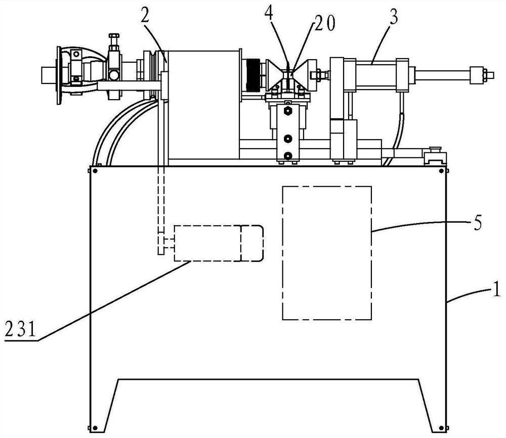
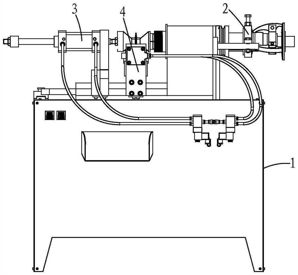
[0064] Rack 1;

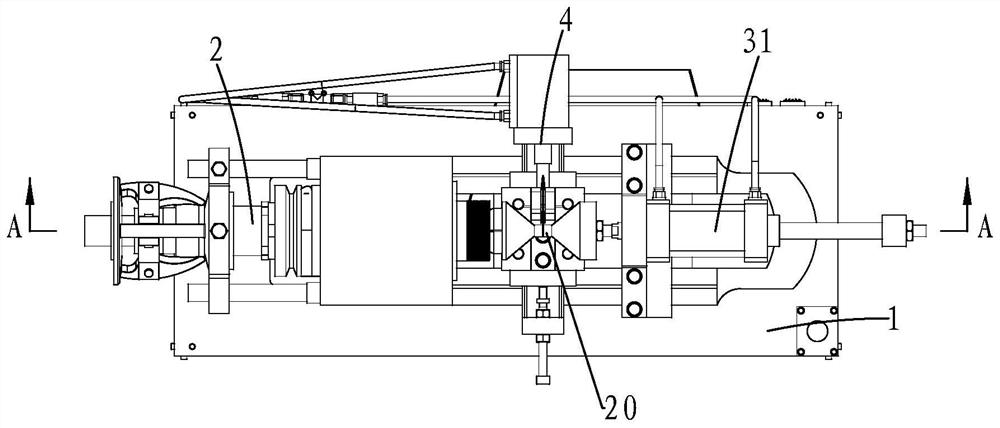
[0065]The instrument car assembly 2, the instrument car assembly 2 includes a mounting base 21, a rotating shaft 22 and a first drive module 23; one end of the rotating shaft 22 is protruded with a first thimble 24, and the axis of the first thimble 24 and the The axes of the rotating shaft 22 coincide; the first driving module 23 is connected to the rotating shaft 22, and the rotating shaft 22 is driven to rotate by the first driving module 23, thereby driving the first thimble 24 to rotate; the rotating shaft 22 Rotationally connected to the mounting base 21, and the first thimble 24 is located on one side of the mounting base 21, and the first thimble 24 is driven by the rotating shaft 22 to perform rotational movement; the mounting base 21 is fixedly connected On the frame 1; the instrument car assembly 2 is existing and can be purchased directly on the market.

[0066...

Embodiment 2

[0077] Embodiment two: on the basis of embodiment one,

[0078] The first drive module 23 includes a motor 231, a first pulley 232, a second pulley 233 and a belt 234; the motor 231 is electrically connected to the control device 5, and the motor 231 is installed on the frame 1; the first pulley 232 is fixedly sleeved on the output shaft of the motor 231; the second pulley 233 is fixedly sleeved on the rotating shaft 22; the belt 234 is sleeved on the first pulley 232 and the second pulley 233. The motor 231 is controlled by the control device 5 through an electric signal to drive the first pulley 232 to rotate, the belt 234 to drive the second pulley 233 to rotate, and then to drive the rotating shaft 22 to rotate, and finally to drive the pulley 232 to rotate. The first thimble 24 rotates.

[0079] The mounting base 21 defines a through hole 211 ; a first bearing 212 is nested in the through hole 211 ; the first bearing 212 is nested on the rotating shaft 22 .

[0080] Th...


PUM


Abstract

The invention provides a semi-automatic channeling machine. The semi-automatic channeling machine comprises a rack, an instrument trolley assembly, am ejector pin assembly, a channeling tool rest assembly and a control device; a direct head of a groove to be machined is arranged between a first ejector pin and a second ejector pin, a second driving module is controlled by the control device to drive the second ejector pin to push the direct head tightly, then the control device controls the channeling tool rest assembly to move for groove machining, when the groove of the product is machined in place, a limiting device pushes against a tool rest, is simultaneously sensed by a sensing device and then fed back to the control device, and finally the control device controls a channeling tool rest group and the ejector pin assembly to reset and stop to finish machining. In the whole process, all machining procedures are all mechanical except manual material placement and starting, the groove structure is automatically machined, the productivity is improved, the product quality is ensured, and production achieves the high-efficiency and high-quality effects.

Description

【Technical field】 [0001] The invention relates to the technical field of mechanical processing equipment, in particular to a semi-automatic rolling groove machine. 【Background technique】 [0002] At present, for some direct head products on water pipes and refrigeration pipes, the groove limit structure in the middle is mostly rolled by a simple manual grooving machine. This kind of production efficiency is relatively slow and the grooves of the processed products have different depths and unstable quality. 【Content of invention】 [0003] The technical problem to be solved by the present invention is to provide a semi-automatic grooving machine, which mechanizes all the processing procedures except feeding and starting, automatically processes the groove structure, improves productivity, and ensures product quality at the same time, so that the production can achieve high efficiency and high quality. Effect. [0004] The present invention is achieved like this: a kind of...

Claims


Application Information

Patent Timeline
Patent Type & Authority Applications(China)
IPC IPC(8): B23B5/00B23B25/06
CPCB23B5/00B23B25/06
Inventor 郑振礼
Owner FUZHOU ZHENXIE PIPE
Why Eureka
Try Eureka