Plate cutting device

A technology for cutting devices and plates, applied in sawing devices, metal sawing equipment, metal processing equipment, etc., can solve the problems of low efficiency and slow speed of cutting gears, and achieve the effect of wide cutting range and high cutting efficiency

Active Publication Date: 2020-10-30
江西千多多家具有限公司
View PDF6 Cites 0 Cited by
  • Summary
  • Abstract
  • Description
  • Claims
  • Application Information

AI Technical Summary

Problems solved by technology

In the process of cutting plates, cutting gears and lasers are generally used for cutting, but the efficiency of direct cutting by cutting gears is mostly not high, and the speed of laser cutting is relatively slow

Method used


Image

  • Plate cutting device
  • Plate cutting device
  • Plate cutting device

Examples


Embodiment 1

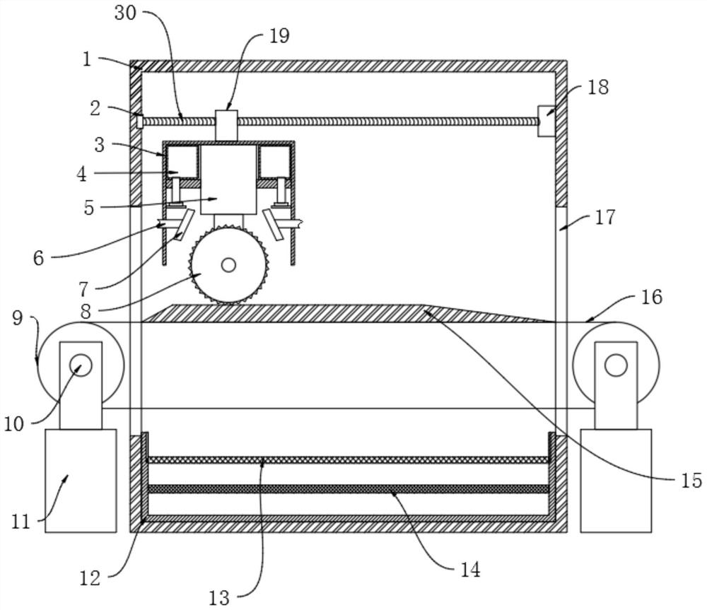
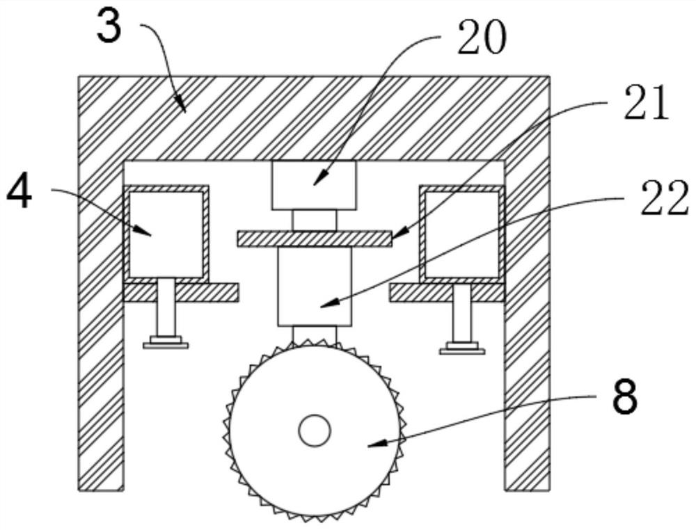
[0021] see Figure 1-5 , a plate cutting device, including a box 1, a transmission structure and a cutting structure, the inside of the box 1 is provided with a transmission structure, the inside of the box 1 is provided with a cutting structure, and the cutting structure includes a lateral movement mechanism , internal control structure 5, anti-splash housing 3, dust suction structure 4, side water pipe 6, spray head 7 and cutting roller 8, a lateral movement mechanism is fixed inside the box 1, and the lateral movement mechanism drives Connect the anti-splash housing 3, the inner end of the anti-splash housing 3 is fixed with an internal control structure 5, the side of the internal control structure 5 is fixed with a dust suction structure, and the side of the anti-splash housing 3 A side water pipe 6 is fixed, a spray head 7 is fixed at the output end of the side water pipe 6, a cutting roller 8 is fixed at the end of the internal control structure 5, and the cutting rolle...

Embodiment 2

[0028] Compared with Embodiment 1, the improvement of this embodiment is that: the bottom collection box 12 is fixed with a solid collection net plate 13 and a magnetic net plate 14, and the solid collection net plate 13 and magnetic net plate 14 are detachable. Firstly, the solids collection screen 13 is used to collect bulky solids, and then the magnetic screen 14 is used to collect finely divided metal residues.

[0029]The working principle of the present invention is: first, drive the connecting roller 9 through the transmission power mechanism, so that the transmission belt 16 transmits the plate to move, and through the guide plate 15, the plate is gradually raised until it reaches the cutting position, and at the same time the fixed column on the transmission belt 16 Push the plate to continue to move forward on the guide plate 15, then use the hydraulic cylinder 11 to lower the conveyor belt 16, and use the cutting structure to cut, that is, use the electric telescopi...


PUM


Abstract

The invention discloses a plate cutting device. The plate cutting device comprises a box body, a conveying structure and a cutting structure, wherein the cutting structure comprises a transverse moving mechanism, an internal control structure, a splash-proof shell, a dust collection structure, a side water pipe, a spray head and a cutting roller; the cutting roller comprises a cutting gear and a fixed gear; the conveying structure comprises hydraulic cylinders, rollers, rotary shafts, a guide plate, a conveying belt and a fixing column; two groups of gears are adopted, namely one group of fixed gear and one group of rotating gear, so that the cutting area between the adjacent gears and a plate is enlarged, the cutting efficiency is higher, a cutting support frame is arranged on the device,the transverse moving mechanism can be used for driving the plate to be transversely cut, a rotating motor can be used for enabling the plate to be longitudinally cut, and the cutting range is wider.

Description

technical field [0001] The invention relates to a plate device, in particular to a plate cutting device. Background technique [0002] Plates generally refer to soft planar materials with a thickness of more than 2 mm and hard planar materials with a thickness of more than 0.5 mm. It also refers to forged, rolled or cast metal plates. In the process of plate cutting, cutting gears and lasers are generally used for cutting, but the efficiency of direct cutting by cutting gears is mostly not high, and the speed of laser cutting is relatively slow. Contents of the invention [0003] The purpose of the present invention is to provide a plate cutting device to solve the problems raised in the background art above. [0004] To achieve the above object, the present invention provides the following technical solutions: [0005] A plate cutting device, comprising a box body, a conveying structure and a cutting structure, the inside of the box body is provided with a conveying st...

Claims


Application Information

Patent Timeline
Patent Type & Authority Applications(China)
IPC IPC(8): B23D45/10B23D47/02B23D47/00
CPCB23D45/10B23D47/00B23D47/02
Inventor 刘裕平
Owner 江西千多多家具有限公司
Why Eureka
Try Eureka