Steel bar rust removal treatment device based on construction site

A processing device and steel bar technology, applied in the direction of spraying device, liquid spraying device, grinding drive device, etc., can solve the problems of low efficiency of rust removal, slow rust removal efficiency of steel bar derusting machine, inconvenient replacement of wire rollers, etc. Achieve the effect of improving the efficiency of rust removal, improving the effect of rust removal, and fast grinding speed

Active Publication Date: 2020-10-30
安徽恒星建设工程有限公司
View PDF7 Cites 0 Cited by
  • Summary
  • Abstract
  • Description
  • Claims
  • Application Information

AI Technical Summary

Problems solved by technology

[0004] The present invention provides a steel bar derusting treatment device based on the construction site, which can effectively solve the problem in the above background technology that when derusting the steel bar at the current construction site, the steel bar derusting machine is generally used to derust the steel bar, but the steel bar derusting machine is used to derust the steel bar. The derusting efficiency of the rust machine is relatively slow, and when the steel wire roll needs to be replaced, the device needs to be disassembled, which is inconvenient for the staff to replace the wire roll, resulting in a problem of low derusting efficiency

Method used


Image

  • Steel bar rust removal treatment device based on construction site
  • Steel bar rust removal treatment device based on construction site
  • Steel bar rust removal treatment device based on construction site

Examples


Embodiment

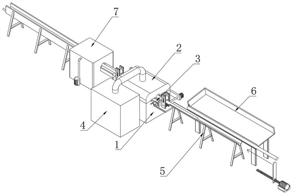
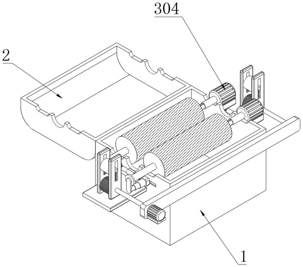
[0057] Example: such as Figure 1-10 As shown, the present invention provides a technical solution, a steel bar derusting treatment device based on a construction site, including a grinding box 1, a box cover 2 is hinged on one side of the top end of the grinding box 1, and a steel bar support frame 5 is placed at one end of the polishing box 1;

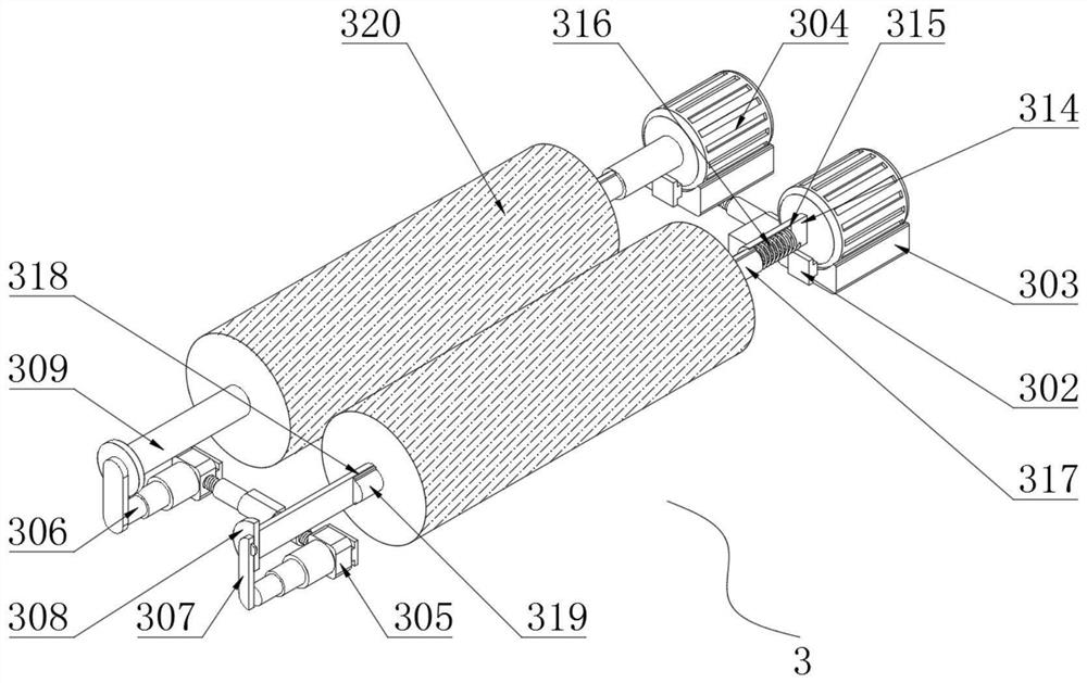
[0058] A high-efficiency grinding and disassembly assembly 3 is installed inside the grinding box 1, and the high-efficiency grinding and disassembly assembly 3 includes a moving slot 301, a moving block 302, a motor seat 303, a grinding motor 304, a mounting block 305, an electric telescopic rod 306, a connecting plate 307, and a fixed plate 308 , installation shaft 309, driving block 310, screw rod 311, threaded cylinder 312, fixed sleeve 313, rotating shaft 314, driving groove 315, tension spring 316, insertion column 317, installation groove 318, installation column 319, wire roller 320 and sliding hole 321;

[0059] Both ends o...


PUM


Abstract

The invention discloses a steel bar rust removal treatment device based on a construction site. The steel bar rust removal treatment device comprises a grinding box, wherein moving grooves are formedin two ends of two sides of the grinding box; a moving block is connected to the inside of each moving groove in a sliding manner; a grinding motor is mounted at the top end of a motor base; screws are movably mounted at one end of a driving block and one end of a mounting block; every two adjacent screws are connected through a threaded cylinder; the outer side of each threaded cylinder is fixedly connected with a fixed sleeve in a sleeving manner; and one end of each fixed sleeve is mounted at one end of the grinding box through a screw. Compared with the prior art, the steel bar rust removal treatment device has the beneficial effects that a worker can conveniently move a steel wire roller and can directly move the steel wire roller from the outside of the grinding box, the problem thatthe worker needs to open a box cover to move the steel wire roller in the prior art is solved, meanwhile, the steel wire roller can be directly moved without closing a machine in the grinding process, the steel bar rust removal treatment device can adapt to steel bars with different specifications in the grinding process, different steel bars are ground, and the grinding efficiency is improved.

Description

technical field [0001] The invention relates to the technical field of steel bar rust removal, in particular to a steel bar rust removal treatment device based on a construction site. Background technique [0002] When the steel bar is not used for a long time at the construction site, the surface of the steel bar is directly in contact with the outside air due to the wind and rain of the external environment, and a slow oxidation reaction occurs, causing the surface of the steel bar to rust, which is rusted in the current construction site Before removing the steel bars, the rusty steel bars need to be derusted to ensure the grip between the steel bars and the concrete. [0003] When derusting the steel bar at the construction site, the steel bar derusting machine is generally used to derust the steel bar, but the derusting efficiency of the steel bar derusting machine is relatively slow, and when the steel wire roller needs to be replaced, the device needs to be disassembl...

Claims


Application Information

Patent Timeline
Patent Type & Authority Applications(China)
IPC IPC(8): B24B27/033B24B41/02B24B41/00B24B47/12B24B41/04B24B55/06B24B55/12B08B1/02B05B9/04B05B14/00
CPCB05B9/0403B08B1/006B08B1/02B24B27/033B24B41/005B24B41/02B24B41/04B24B47/12B24B55/06B24B55/12B05B14/00
Inventor 谭梅珍
Owner 安徽恒星建设工程有限公司
Why Eureka
Try Eureka