Canned fruit processing equipment
A technology for processing equipment and canned fruit, which is applied in the field of canned fruit processing equipment, and can solve the problems of inconvenient collection of fruit pieces and inability to peel fruit
- Summary
- Abstract
- Description
- Claims
- Application Information
AI Technical Summary
Problems solved by technology
Method used
Image
Examples
Embodiment 1
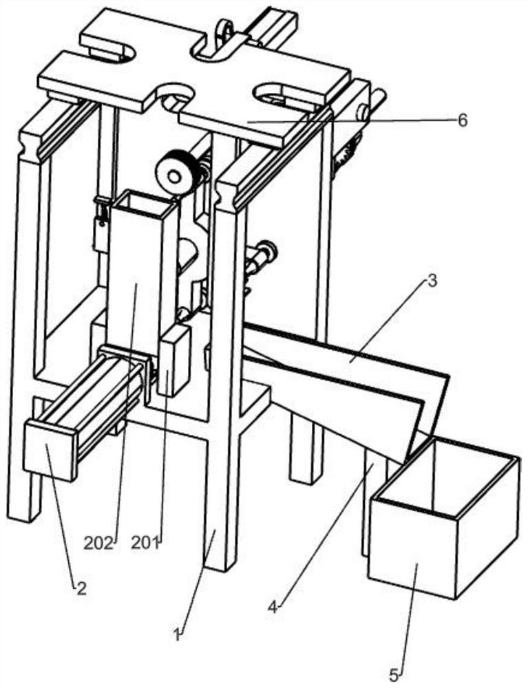
[0028] A kind of canned fruit processing equipment, such as figure 1 , Figure 4 , Figure 7 , Picture 8 with Picture 9 As shown, it includes a bracket 1, a pushing mechanism 2, a lower hopper 3, a pillar 4, a collection box 5, a moving mechanism 6, a missing gear 7, a shaft 5 8, a spur gear 9, a fixed frame 10, a fixed rod 11, and a stop 12. Spring one 13, support plate one 14, fixed block 15, pin three 17, cutter 18 and spring two 19, the pusher mechanism 2 is installed on the support 1, and the support 1 on the right side of the pusher mechanism 2 is embedded Lower hopper 3, the bottom of the lower hopper 3 is equipped with a pillar 4, a collection box 5 is placed on the ground under the lower hopper 3, the moving mechanism 6 is set on the top of the bracket 1, and the moving mechanism 6 is provided with a missing gear 7, a missing gear 7 The upper bracket 1 is rotatably provided with a rotating shaft 518, a spur gear 9 is fixed on the rotating shaft 5.8, and the spur gear...
Embodiment 2
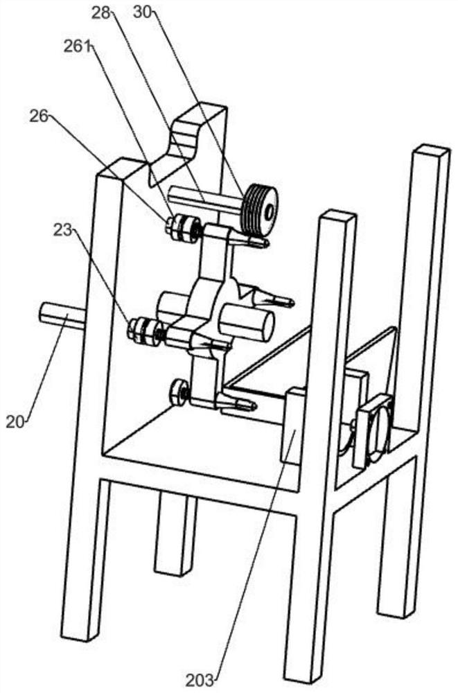
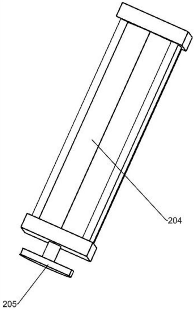
[0031] On the basis of Example 1, such as figure 1 , figure 2 with image 3 As shown, the pushing mechanism 2 includes a vertical plate 201, a feeding box 202, a containing frame 203, a cylinder 204, and a pushing plate 205. There are two vertical plates 201, both of which are fixed on the bracket 1. The two vertical plates 201 A blanking box 202 is arranged between the tops, and a holding frame 203 is installed on the bracket 1 between the two vertical plates 201. The holding frame 203 is located directly under the blanking box 202, and the bracket 1 on the front side of the holding frame 203 A cylinder 204 is installed on the upper part by bolts, and a push plate 205 is fixed on the telescopic rod of the cylinder 204, and the push plate 205 is located on the front side of the containing frame 203.
[0032] When the fruit needs to be processed, the user puts the fruit in the feeding box 202, and the fruit in the feeding box 202 drops downwards into the containing frame 203, and ...
Embodiment 3
[0034] On the basis of Example 2, such as figure 1 , Figure 4 , Figure 5 with Image 6 As shown, the moving mechanism 6 includes a sliding rail 601, a slider 602, a top plate 603, a fixed plate 604, a fixed plate 605, a mounting plate 606, a guide plate 607, a rotating shaft 608, a swing plate 609, a pin rod 611, Connecting plate 612, rotating shaft two 613, helical gear one 614, disc 615, pin two 616, mounting plate two 617, rotating shaft three 618, helical gear two 619, pulley one 620, rotating shaft four 621, pulley two 622, Belt one 623, pulley three 624, mounting plate three 625, geared motor 626, first double-groove pulley 627 and belt two 628, there are two slide rails 601, both of which are set on the left and right sides of the top of bracket 1, slide rails There are two sliding blocks 602 on the 601, the top plate 603 is fixed between the tops of the four sliding blocks 602, the supporting plate 14 is fixed to the rear side of the bottom of the top plate 603, and th...
PUM
 Abstract
Description
Claims
Application Information
 - R&D
- Intellectual Property
- Life Sciences
- Materials
- Tech Scout
- Unparalleled Data Quality
- Higher Quality Content
- 60% Fewer Hallucinations
Browse by: Latest US Patents, China's latest patents, Technical Efficacy Thesaurus, Application Domain, Technology Topic, Popular Technical Reports.
© 2025 PatSnap. All rights reserved.Legal|Privacy policy|Modern Slavery Act Transparency Statement|Sitemap|About US| Contact US: help@patsnap.com


