Automatic control device of glass kiln

An automatic control device and glass furnace technology, which is applied in glass furnace equipment, glass manufacturing equipment, manufacturing tools, etc., can solve the problem that the flame length control cannot be realized quickly and accurately, affects the temperature of the melting part in the glass furnace, and cannot be carried out quickly and synchronously Changes and other issues, to achieve fast and flame length, precise flame length, precise control effect

Inactive Publication Date: 2020-10-30
来安县华阳玻璃制品有限公司
View PDF0 Cites 1 Cited by
  • Summary
  • Abstract
  • Description
  • Claims
  • Application Information

AI Technical Summary

Problems solved by technology

[0003] At present, the gas supply of the glass kiln needs to be preheated through the heat storage tank, and then supplied to the flame spray gun through the valve. After the gas is preheated through the heat storage tank and enters the process of the flame spray gun, the gas flow is not stable enough, which will easily lead to The length of the flame is affected, thereby affecting the temperature of the melting part in the glass kiln. At present, when controlling the length of the flame, a temperature measuring device is generally installed on the side wall of the kiln to detect the temperature of the kiln. Through the valve Control the amount of gas to adjust the length of the flame. The heat-resistant effect of the temperature measuring device is relatively poor. It must be installed in the low-temperature zone of the kiln for detection. However, when the flame length changes, the temperature in the low-temperature zone inside the kiln cannot be quickly synchronized. Variations such that the control of the flame length cannot be achieved quickly and precisely
[0004] When the flame spray gun is working, the preheated combustion-supporting air needs to be fed at the same time. When the combustion-supporting air enters the flame spray gun, a large amount of water vapor still remains, so that the combustion-supporting air still contains moisture in the glass kiln. Affect the quality of glass

Method used


Image

  • Automatic control device of glass kiln
  • Automatic control device of glass kiln
  • Automatic control device of glass kiln

Examples


Embodiment Construction

[0019] The following will clearly and completely describe the technical solutions in the embodiments of the present invention with reference to the accompanying drawings in the embodiments of the present invention. Obviously, the described embodiments are only some, not all, embodiments of the present invention. Based on the embodiments of the present invention, all other embodiments obtained by persons of ordinary skill in the art without making creative efforts belong to the protection scope of the present invention.

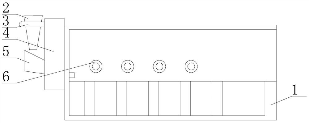
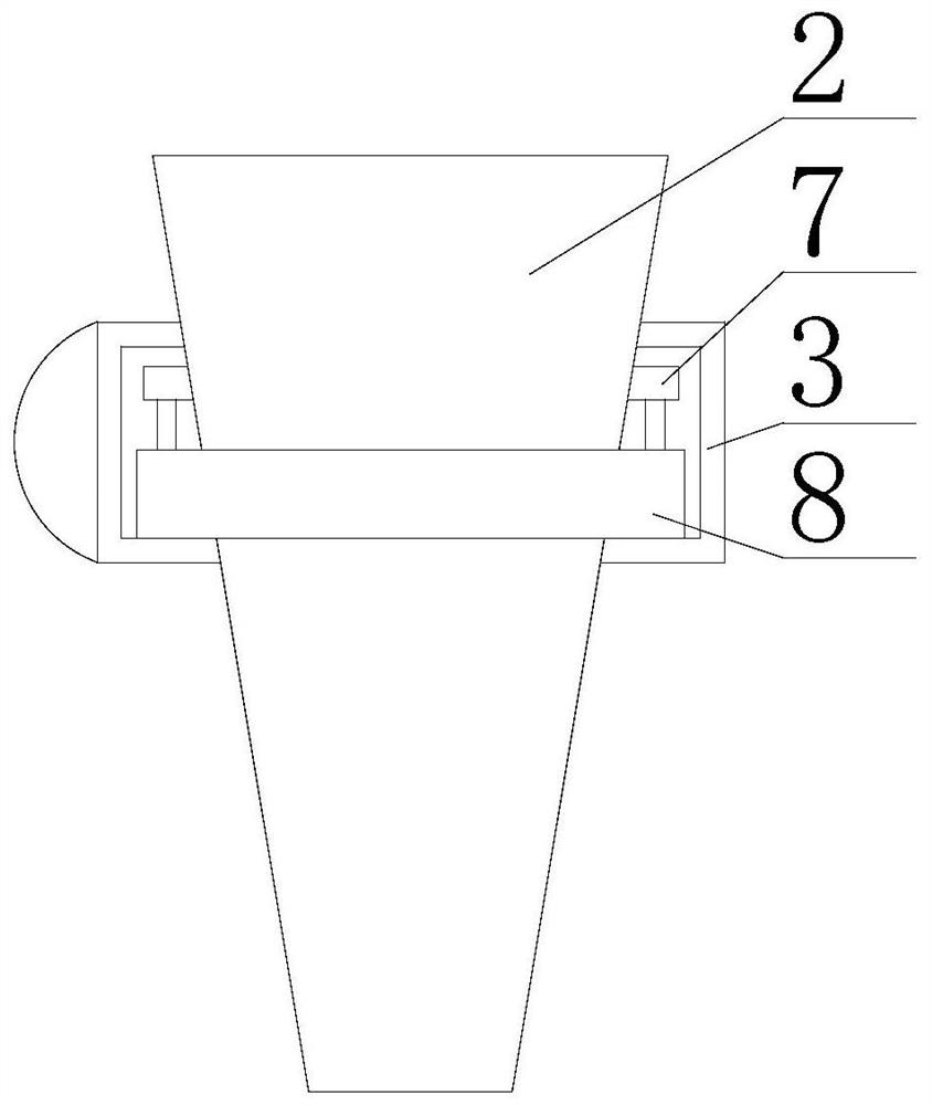
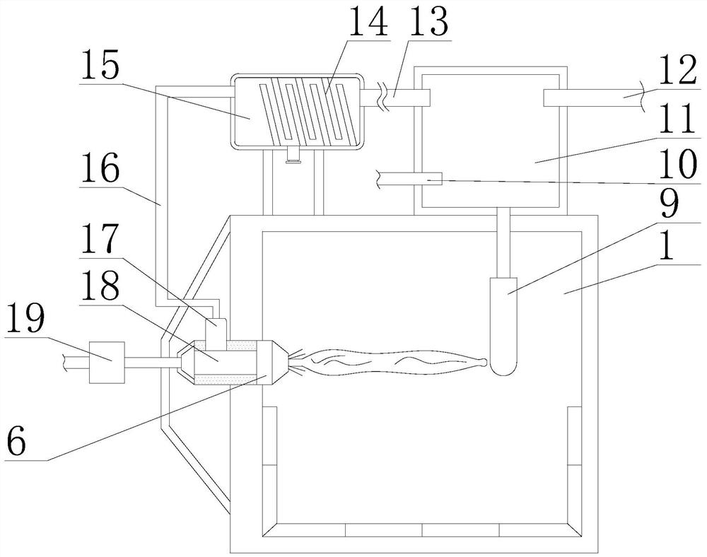
[0020] see Figure 1-4 , an automatic control device for a glass kiln, comprising a kiln body 1, a side support plate 4 is fixedly installed on the left side of the kiln body 1, and a weighing support seat 3 is fixedly installed on the left side of the side support plate 4. The bottom of the inner cavity of the support seat 3 is fixedly equipped with a cylindrical weighing scale 8, and the top of the cylindrical weighing scale 8 is fixedly connected with a sup...


PUM


Abstract

The invention relates to the technical field of glass kiln control equipment. The invention further discloses an automatic control device of a glass kiln. The automatic control device comprises a kilnbody, a side face supporting plate is fixedly mounted on the left side face of the kiln body, a weighing supporting base is fixedly mounted on the left side of the side face supporting plate, a cylindrical measuring scale is fixedly mounted at the bottom of an inner cavity of the weighing supporting base, and a supporting sleeve base is fixedly connected to the top of the cylindrical measuring scale. According to the automatic control device of the glass kiln, a sealing steel cylinder is arranged in the kiln body, a gas storage box is arranged above the kiln body, and a gas bag is matched with a spring, so when the flame length of a flame spray gun cannot touch the sealing steel cylinder, the temperature of the sealing steel cylinder is reduced, and thus the gas bag communicated with thegas storage tank is compressed, a valve plate is driven by the spring to move, the gas inflow amount of the valve seat is increased, the flame length is increased until a balance state is achieved, and the flame length can be quickly and accurately controlled.

Description

technical field [0001] The invention relates to the technical field of glass kiln control equipment, in particular to an automatic control device for a glass kiln. Background technique [0002] During the working process of the glass furnace, the glass furnace has requirements on the length of the flame in the melting pool, because the length of the flame exiting the crater has a great influence on the temperature of the flame space in the melting pool, the temperature of the glass liquid surface and the temperature inside the large flame. The surface temperature and the liquid flow direction of the molten glass in the melting pool will have varying degrees of influence, and the flame length is generally two-thirds of the width of the glass furnace. [0003] At present, the gas supply of the glass kiln needs to be preheated through the heat storage tank, and then supplied to the flame spray gun through the valve. After the gas is preheated through the heat storage tank and e...

Claims


Application Information

Patent Timeline
Patent Type & Authority Applications(China)
IPC IPC(8): C03B5/235C03B3/00
CPCC03B3/00C03B5/235
Inventor 杜存武
Owner 来安县华阳玻璃制品有限公司
Why Eureka
Try Eureka