Automatic microorganism culture monitoring analyzer
A technology of microorganisms and analyzers, applied in the field of machinery, can solve the problems of lack of objectivity and authenticity of test results, inability to record the actual situation of microorganism growth on the culture medium, and lack of data.
- Summary
- Abstract
- Description
- Claims
- Application Information
AI Technical Summary
Problems solved by technology
Method used
Image

Examples
Embodiment 1
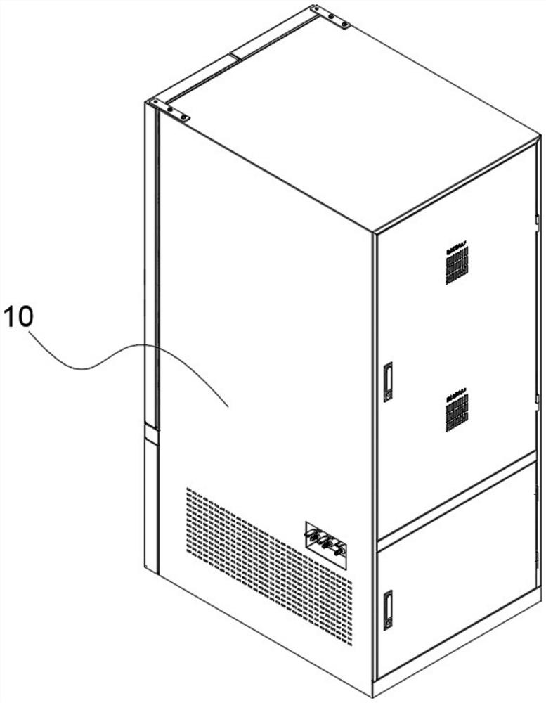
[0071] Such as Figure 1-Figure 16 As shown, a microbial automatic culture monitoring analyzer includes an analysis cabinet 10 and a tray 205 placement device 20 arranged in the analysis cabinet 10, a monitoring device 30, a temperature control device 40 and a main control device 50, and the analysis cabinet 10 is The partition 60 is divided up and down into a control area 101 and a placement area 102, the control device is arranged in the control area 101, and the tray 205 placement device 20 and the temperature control device 40 are arranged in the placement area 102;
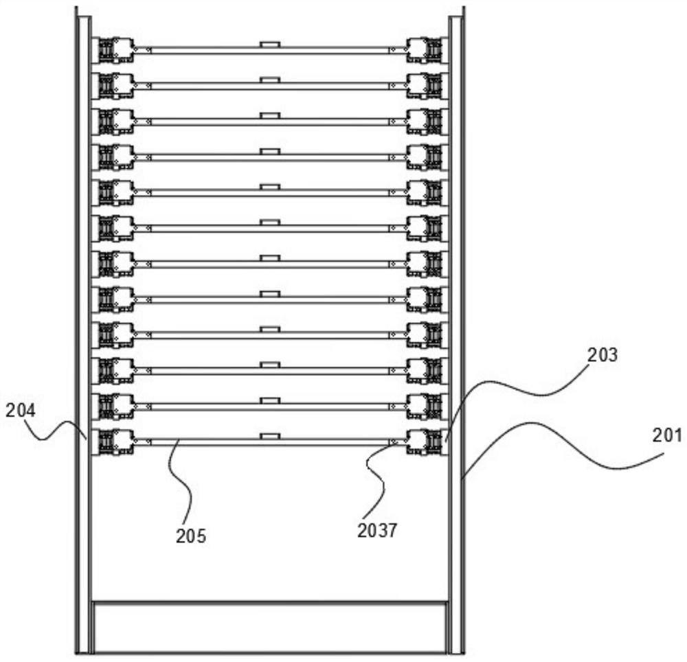
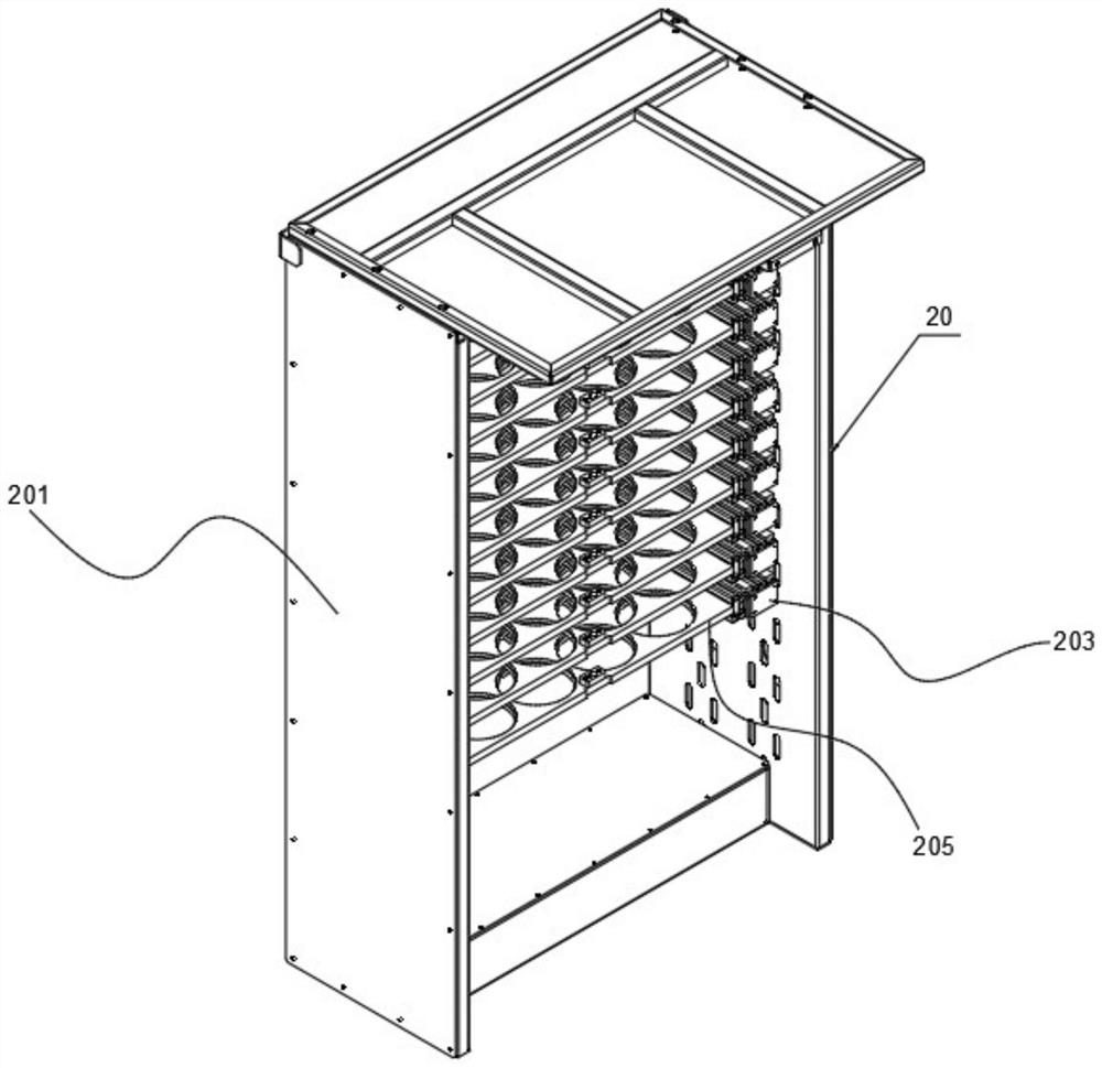
[0072]The tray 205 placement device 20 includes an installation frame 201 and a number of petri dish placement mechanisms 202, the installation rack is vertically arranged in the placement area 102 and close to the cabinet door of the analysis cabinet 10, on the installation rack The petri dish placement mechanism 202 is arranged horizontally from bottom to top; the petri dish placement mechanism 202 includes...
Embodiment 2
[0079] Such as Figure 11-Figure 13 As shown, this embodiment is based on Embodiment 1, the partition 60 includes a first connecting plate 601, a second connecting plate 602 and a third connecting plate 603, and the first connecting plate 601 is located in the analysis On the inner side wall of the cabinet 10 body, and on the side of the cabinet door of the analysis cabinet 10 body, the longitudinal section of the second connecting plate 602 is in the shape of "concave", and the side wall of the second connecting plate 602 is in line with the The inner side wall of the analysis cabinet 10 body is connected, the third connecting plate 603 is arranged on the top of the second connecting plate 602, and the top of the second connecting plate 602 is provided with a fixing cylinder 604 with two ends open. The fixing cylinder 604 is adapted to the cultivation area, and the fixing cylinder 604 is provided with the installation plate 301 on the side of the cabinet door away from the an...
Embodiment 3
[0083] Such as Figure 2-Figure 8 As shown, this embodiment is based on Embodiment 1, the first connecting mechanism 203 includes a first connecting piece 2031, a first sliding piece 2032, a second connecting piece 2033 and a second sliding piece 2034 connected in sequence, so The first connecting piece 2031 is connected to the installation frame 201, the second sliding piece 2034 is provided with a slot 2035 for installing the tray 205, and the second connecting piece 2033 and the tray 205 pass through The magnet 2036 is connected with the first auxiliary connecting plate 2037, the second connecting member 2033 and the first connecting member 2031 are connected with the second auxiliary connecting plate 2038 through the magnet 2036, the first sliding member 2032 and the The second sliding part 2034 is provided with a sliding limiter 20329, the sliding limiter plate on the first sliding part 2032 is close to the cabinet door of the microbial automatic analyzer, the sliding par...
PUM
 Abstract
Description
Claims
Application Information
 - R&D
- Intellectual Property
- Life Sciences
- Materials
- Tech Scout
- Unparalleled Data Quality
- Higher Quality Content
- 60% Fewer Hallucinations
Browse by: Latest US Patents, China's latest patents, Technical Efficacy Thesaurus, Application Domain, Technology Topic, Popular Technical Reports.
© 2025 PatSnap. All rights reserved.Legal|Privacy policy|Modern Slavery Act Transparency Statement|Sitemap|About US| Contact US: help@patsnap.com