
Four-direction displacement geotechnical bridge handrail concrete pouring device

A concrete and bridge technology, applied in the direction of bridges, bridge parts, bridge construction, etc., can solve the problems of small concrete volume, affecting quality, low efficiency, etc., to achieve the effect of guaranteed strength, strong integrity and precise steering

Active Publication Date: 2020-10-30
INNER MONGOLIA AGRICULTURAL UNIVERSITY +1
View PDF9 Cites 6 Cited by
  • Summary
  • Abstract
  • Description
  • Claims
  • Application Information

AI Technical Summary

Problems solved by technology

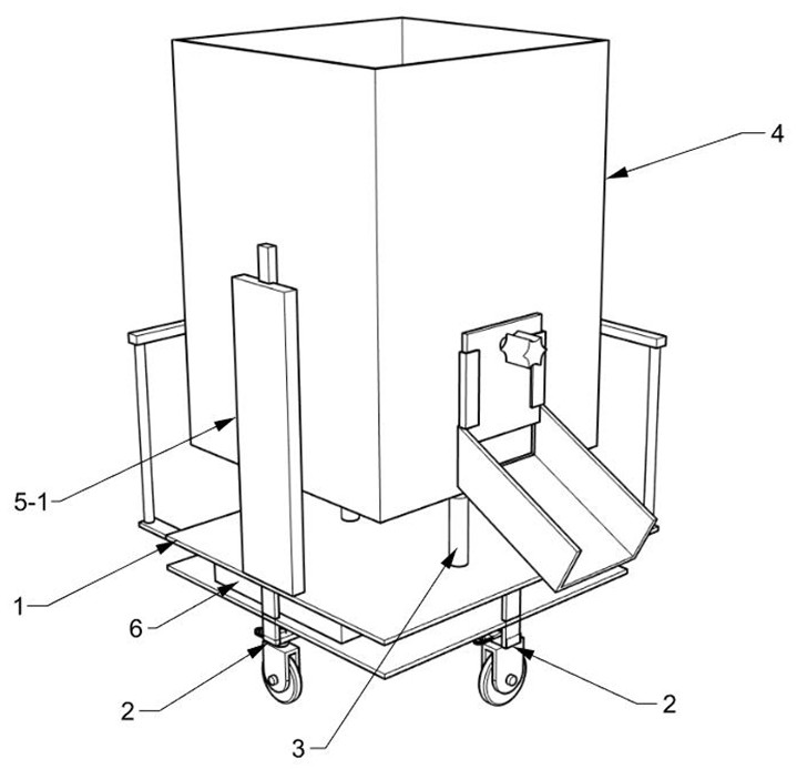
[0003] At present, the unit length of bridge railings requires a small amount of concrete. It is uneconomical to use large pouring equipment such as concrete pumps and pump trucks. General construction parties do not use such equipment for pouring in order to save costs. Most of them use small carts, The dump truck transports the concrete to the pouring position, and then pours the concrete into the bridge railing mold; in the actual operation process, the railing is higher than the bridge deck at a certain height, so there is a certain height difference between the railing mold and the bridge deck, small carts, dump trucks, etc. , it is impossible to adjust the corresponding height according to the situation on site, the applicability is low, and the concrete can only be filled into the bridge railing manually, which is very inefficient and consumes physical strength; The setting time of high-level concrete is inconsistent, which greatly affects the quality, and the bridge railings after forming often have cracks, which greatly affects safety
[0004] At the same time, the current solution (equipment) cannot control the poured concrete flow during the pouring process, which affects work efficiency, so it needs to be improved

Method used


Image

  • Four-direction displacement geotechnical bridge handrail concrete pouring device
  • Four-direction displacement geotechnical bridge handrail concrete pouring device
  • Four-direction displacement geotechnical bridge handrail concrete pouring device

Examples


Embodiment Construction

[0029] The following will clearly and completely describe the technical solutions in the embodiments of the present invention with reference to the accompanying drawings in the embodiments of the present invention. Obviously, the described embodiments are only some of the embodiments of the present invention, not all of them.

[0030] In describing the present invention, it should be understood that the terms "upper", "lower", "front", "rear", "left", "right", "top", "bottom", "inner", " The orientation or positional relationship indicated by "outside", etc. is based on the orientation or positional relationship shown in the drawings, and is only for the convenience of describing the present invention and simplifying the description, rather than indicating or implying that the referred device or element must have a specific orientation, so as to Specific orientation configurations and operations, therefore, are not to be construed as limitations on the invention.

[0031] Plea...


PUM


Abstract

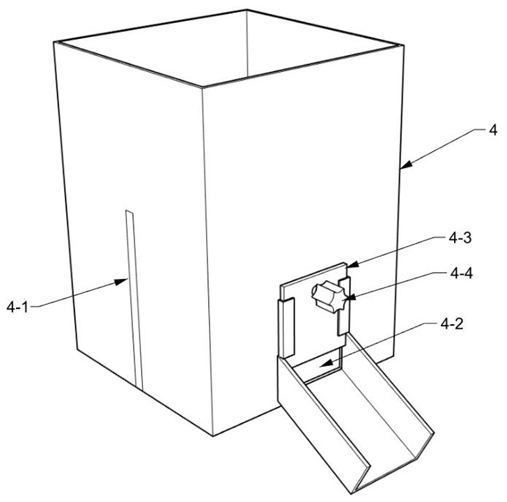
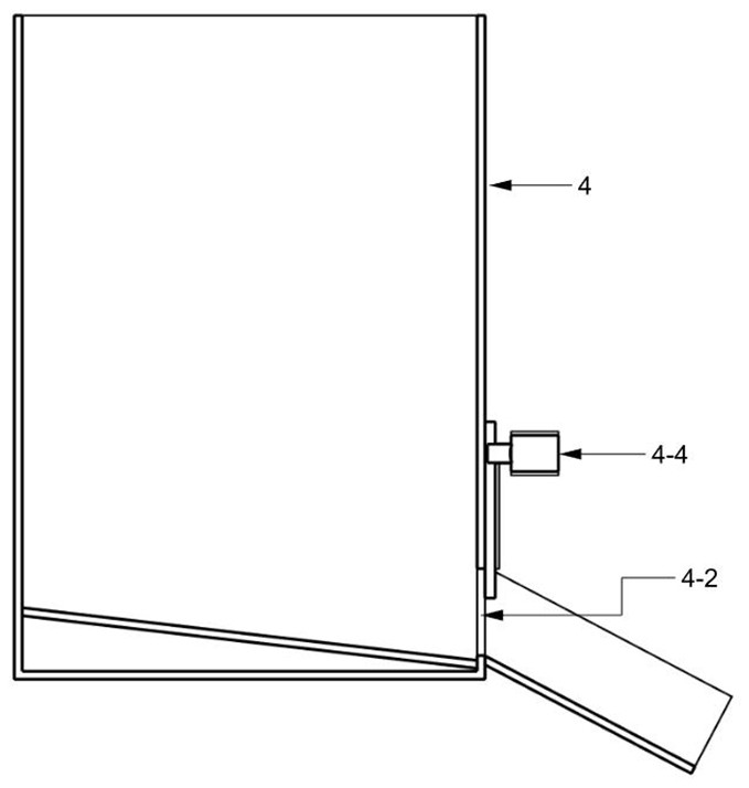
The invention discloses a four-direction displacement geotechnical bridge handrail concrete pouring device. The geotechnical bridge handrail concrete pouring device comprises a chassis, wheel systems,a hydraulic rod and a storage box. Two sets of wheel systems are installed on the lower surface of the chassis and arranged in a crossed mode. The storage box is arranged on the upper surface of thechassis in an up-down sliding mode, the hydraulic rod is arranged between the storage box and the chassis, and the hydraulic rod pushes the storage box to move up and down; L-shaped push handles are arranged on the adjacent side edges of a bottom frame; each wheel system comprises a wheel bridge, a wheel arm, a roller, a steering rod, a connecting rod and a rack; and the wheel arms are rotatably installed below the two ends of the wheel bridges, and the rollers are installed on the wheel arms. The device is specially used for pouring construction of a bridge handrail, prepared concrete can berapidly poured into a handrail mold of a bridge through the device, and meanwhile the height of a discharging opening can be adjusted according to the height of the handrail so as to achieve adaptation. According to wheel layout, steering can be well controlled, and rapid and accurate positioning to a target area can be achieved.

Description

technical field [0001] The invention relates to the field of civil engineering, in particular to a four-way displacement concrete pouring device for railings of geotechnical bridges. Background technique [0002] Concrete is one of the most important civil engineering materials in the contemporary era. It refers to a mixture made of cement, granular aggregate, water, admixtures and mineral admixtures that need to be added in an appropriate proportion; After a certain period of physical and chemical changes in the enclosed space of a certain shape, a structure with high compressive strength, good durability, a wide range of strength levels, and a shape that meets the design requirements is formed. Common concrete pouring equipment such as concrete pumps and concrete pumps Cars, belt transport pouring equipment, cranes with pouring devices, etc., are used for pouring large concrete structures. Small trolleys and dump trucks are often used for concrete pouring of structures be...

Claims


Application Information

Patent Timeline
Patent Type & Authority Applications(China)
IPC IPC(8): E01D19/10E01D21/00
CPCE01D19/103E01D21/00
Inventor 高明星丁杰李航天关鹏方淑艳史宏江吴淑杰
Owner INNER MONGOLIA AGRICULTURAL UNIVERSITY
Learn More