Eureka AIR delivers breakthrough ideas for toughest innovation challenges, trusted by R&D personnel around the world.

Movable straw incineration device

An incinerator, mobile technology, applied in incinerators, combustion methods, combustion types, etc., can solve problems such as inconvenience, time-consuming and laborious, and air pollution.

Inactive Publication Date: 2020-10-30
白木日根
View PDF0 Cites 1 Cited by
  • Summary
  • Abstract
  • Description
  • Claims
  • Application Information

AI Technical Summary

Problems solved by technology

[0002] Straw refers to the remaining stems and leaves of gramineous crops such as rice, wheat, and corn after threshing. With the progress of society, due to the popularization of coal, electricity, and natural gas, and the abundance of various industrial products, the demand for straw in rural areas has decreased. , the disposal of a large amount of straw has become a serious social problem. Although it is prohibited by law, farmers in many places still directly burn straw in the fields, causing air pollution, fires, and the failure of planes to take off and land normally.
[0003] Therefore, there are straw incinerators on the market, which are used to incinerate straws. However, the existing straw incineration devices are generally unable to move, requiring the user to collect and pack the straws, and then burn them uniformly, which is time-consuming and laborious, and it is inconvenient to use.

Method used


Image

  • Movable straw incineration device
  • Movable straw incineration device
  • Movable straw incineration device

Examples


Embodiment Construction

[0028] The present invention is described in further detail now in conjunction with accompanying drawing. These drawings are all simplified schematic diagrams, which only illustrate the basic structure of the present invention in a schematic manner, so they only show the configurations related to the present invention.

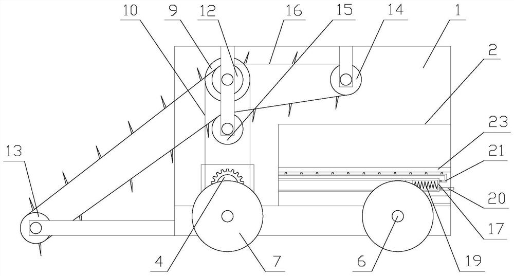
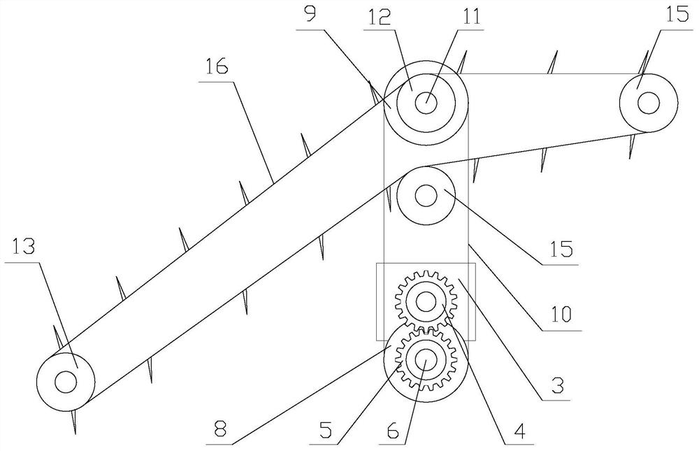
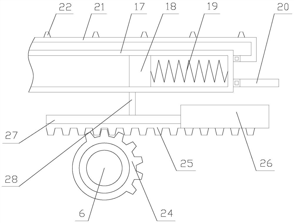
[0029] Such as figure 1 As shown, a mobile straw incineration device includes a car body 1, a combustion furnace 2, a driving mechanism, a transmission mechanism and an air blowing mechanism. The car body 1 is hollow, and the combustion furnace 2 is arranged in the car body 1. The driving mechanism is arranged on the car body 1, the transmission mechanism is arranged at one end of the car body 1, and the air blowing mechanism is arranged in the combustion furnace 2;

[0030] The device drives the car body 1 to move through the driving mechanism, transmits the straw in the field to the combustion furnace 2 through the transmission mechanism, and blows the comb...


PUM


Abstract

The invention relates to a movable straw incineration device. The movable straw incineration device comprises a vehicle body, a combustion furnace, a driving mechanism, a conveying mechanism and an air blowing mechanism; the vehicle body is hollow, the combustion furnace is arranged in the vehicle body, the driving mechanism is arranged on the vehicle body, the conveying mechanism is arranged at one end of the vehicle body, and the air blowing mechanism is arranged in the combustion furnace. According to the movable straw incineration device, movement of the vehicle body is achieved through the driving mechanism, straws are conveyed into the combustion furnace through the conveying mechanism to be incinerated, air blowing is conducted in the combustion furnace through the air blowing mechanism, and a better incineration effect is achieved, and compared with an existing straw incineration device, the movable straw incineration device has the advantages that through linkage of a drivingassembly and a conveying assembly, and the online collection and incineration of the straws are realized; compared with an existing air blowing mechanism, the mechanism has the advantages that automatic air blowing is achieved through linkage of a mechanical structure when the vehicle body moves, an independent driving source is not needed, and energy is saved.

Description

technical field [0001] The invention relates to a mobile straw burning device. Background technique [0002] Straw refers to the remaining stems and leaves of gramineous crops such as rice, wheat, and corn after threshing. With the progress of society, due to the popularization of coal, electricity, and natural gas, and the abundance of various industrial products, the demand for straw in rural areas has decreased. , the disposal of a large amount of straw has become a serious social problem. Although it is prohibited by law, farmers in many places still burn straw directly in the fields, causing air pollution, fires, and the failure of planes to take off and land normally. [0003] Therefore, there are straw incinerators on the market, which are used to incinerate straws. However, the existing straw incineration devices are generally unable to move, requiring the user to collect and pack the straws, and then burn them uniformly, which is time-consuming and labor-intensive, ...

Claims


Application Information

Patent Timeline
IPC IPC(8): F23G7/10F23G5/40F23G5/44F23L5/04
CPCF23G5/40F23G5/444F23G7/10F23G2203/601F23G2209/262F23L5/04
Inventor 白木日根
Owner 白木日根
Why Eureka
Eureka Blog
Learn More