Electrothermal blasting drying box for raw material treatment in ore detection process

A technology of electric blast drying and raw material treatment, which is applied in the direction of static material dryer, solid material drying, drying room/container, etc. It can solve the problems of limiting raw material specifications, ore materials cannot be put in, and poor applicability, etc. Achieve the effect of avoiding placing space, maximizing the quantity of placing raw materials, and being flexible and convenient to adjust

Active Publication Date: 2020-10-30
北京中科光析科学技术研究所
View PDF8 Cites 4 Cited by
  • Summary
  • Abstract
  • Description
  • Claims
  • Application Information

AI Technical Summary

Problems solved by technology

[0004] At present, in the existing electric blast drying oven, the storage boards are either placed at fixed intervals, or the storage boards are inserted into the chutes of different heights on both sides of the electric blast drying oven to change the spacing between the storage boards, but in this way There will be some problems: the space between the storage boards with fixed spacing cannot be flexibly adjusted according to the size and specifications of the raw materials, and the applicability is not good; Although the distance between the storage boards can be adjusted, the distance adjusted each time is fixed. For example, the height of an ore raw material is only higher than the distance between two storage boards arranged in adjacent chutes. One point, then the ore raw material cannot be put down if the storage boards are placed adjacent to each other, and since the distance between the chutes is fixed, if there is a chute between the storage boards, the space is relatively large, and the ore raw material is placed It will waste space, and it will also cause the storage space of other storage boards to be compressed, which is very inconvenient to use, and the specifications of raw materials are relatively limited;
[0005] Or individually set up a plurality of chutes to realize the structure of minimizing the distance between the chutes, but due to the distance between the chutes and the chutes, it must be able to carry the weight of the storage board and the ore raw material, so the chute and the chute The distance between the slots always exists and is unavoidable, so there will still be problems that the ore material cannot be placed in the adjacent state of the storage board, and the gap state wastes space;
[0006] In addition, when placing ore materials on the storage board, because the staff's judgment on the comparison between the height of the ore and the distance between the storage boards is not accurate, there is a problem that after placing the ore raw materials, it is found that the distance between the storage boards can be placed. , at this time, in order to leave space for other storage boards, the storage board will be adjusted, either take out the raw materials and adjust the position of the storage board and then put them back, or directly adjust the storage board with the raw materials, no matter which methods are time consuming

Method used


Image

  • Electrothermal blasting drying box for raw material treatment in ore detection process
  • Electrothermal blasting drying box for raw material treatment in ore detection process
  • Electrothermal blasting drying box for raw material treatment in ore detection process

Examples


Embodiment 1

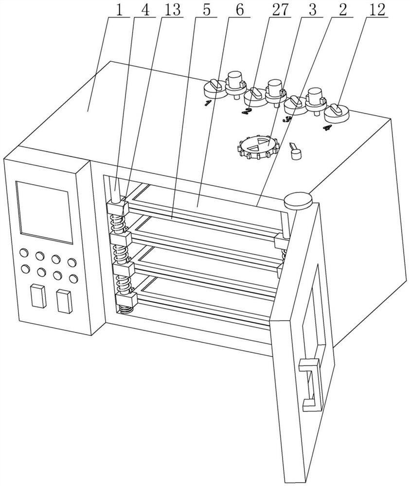
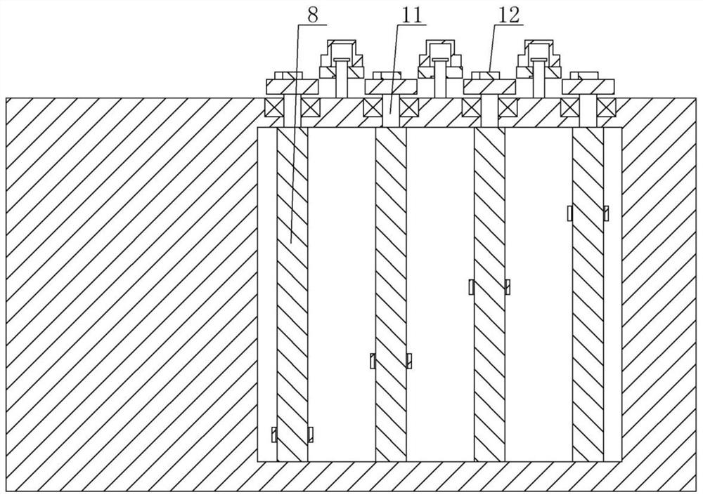
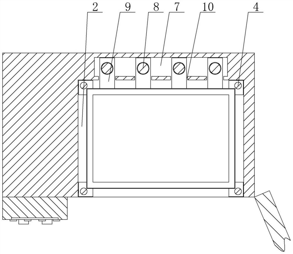
[0037] Embodiment 1: An electric blast drying box for raw material processing in the ore detection process, including a device main body 1, a working chamber 2 is provided inside the device main body 1, a vent cap 3 is provided on the device main body 1, and the The ventilation cap 3 includes a fixed block 21 installed on the top of the device main body 1, the fixed block 21 is provided with a first heat dissipation hole 22 penetrating through the device main body 1, and the outer rotation of the fixed block 21 is covered with a cap 23, the cap 23 The second heat dissipation hole 24 is provided on the top, and the coincidence exposure and dislocation shielding of the first heat dissipation hole 22 can be realized by rotating the cap 23. A plurality of dials 25 are arranged on the outside of the cap 23, and the main body of the device 1 passes through a Rotating lever is provided with driving lever 26, and described driving lever 26 is positioned at ventilation cap 3 one side, a...

Embodiment 2

[0040] Embodiment 2: An electric blast drying box for raw material processing in the ore detection process, including a device main body 1, a working chamber 2 is provided inside the device main body 1, and a ventilation cap 3 is provided on the device main body 1,

[0041] The working cavity 2 is provided with 4 stop rods 4, and 5 support frames 5 are slidably arranged on the stop rod 4, and a storage plate 6 is arranged on the support frame 5, and the support frame 5 includes a right-angle block 28 and a rectangular frame plate 29, the four corners of the rectangular frame plate 29 are respectively arranged in the corners of the right-angle block 28, the thickness of the rectangular frame plate 29 is less than the thickness of the right-angle block 28, and the bottom surface of the rectangular frame plate 29 is in contact with the The bottom surfaces of the right-angle blocks 28 are coplanar, and the rectangular frame plate 29 is provided with a storage board 6, and the four ...


PUM


Abstract

The invention discloses an electrothermal blasting drying box for raw material treatment in an ore detection process and mainly relates to the field of ore detection. The electrothermal blasting drying box comprises an equipment main body. A plurality of limiting rods are arranged in a work cavity. A plurality of bearing frames are slidably arranged on the limiting rods and are provided with a holding plate. A cavity located on one side of the work cavity is formed in the equipment main body. A plurality of screws are rotationally arranged in the cavity, and the number of the screws is the same as that of the bearing frames. One bearing frame corresponds to one screw. Each bearing frame is connected with the corresponding screw through a sliding plate. The screws penetrate through the sliding plates and are in threaded connection with the sliding plates. A plurality of sliding grooves communicating with the cavity are formed in one side of the work cavity. The sliding plates are slidably connected with the sliding grooves. The electrothermal blasting drying box has the beneficial effects that the holding plate can be installed without the need for the sliding grooves, the holding plate can be adjusted at any height in the work cavity, adjustment is convenient, and labor is saved.

Description

technical field [0001] The invention relates to the field of ore detection, in particular to an electric blast drying oven for raw material processing in the ore detection process. Background technique [0002] Ore refers to mineral aggregates from which useful components can be extracted or which have certain properties that can be utilized. It can be divided into metallic minerals and non-metallic minerals. When many material manufacturers purchase raw materials, they will conduct certain tests and analyzes on the ore to determine whether it is suitable for their product requirements. [0003] In the ore testing process, sometimes the raw materials need to be pre-dried before testing, and the electric blast drying box is an important equipment used in it. [0004] At present, in the existing electric blast drying oven, the storage boards are either placed at fixed intervals, or the storage boards are inserted into the chutes of different heights on both sides of the elec...

Claims


Application Information

Patent Timeline
Patent Type & Authority Applications(China)
IPC IPC(8): F26B9/06F26B21/00F26B25/18F26B25/00
CPCF26B9/06F26B21/001F26B21/004F26B25/18F26B25/00
Inventor 高俊广董芝齐根望
Owner 北京中科光析科学技术研究所
Why Eureka
Try Eureka