
Blind hole method based residual stress distribution measurement method for composite material plate

A composite material and residual stress technology, applied in force/torque/work measuring instruments, measuring devices, analysis materials, etc., can solve problems such as error, single measurement stress direction, and large stress gap, so as to improve scientificity and accuracy , flexible and accurate measurement, the effect of precise measurement

Inactive Publication Date: 2020-10-30
DALIAN UNIV OF TECH
View PDF9 Cites 4 Cited by
  • Summary
  • Abstract
  • Description
  • Claims
  • Application Information

AI Technical Summary

Problems solved by technology

However, such methods are costly and require high levels of equipment and personnel, which is not conducive to practical engineering applications.
Destructive testing is widely used in engineering practice, mainly including blind hole method and cutting method. For composite materials with anisotropy, incremental cutting method is often used, but in practical applications, incremental cutting method has Disadvantages such as large damage, single measurement stress direction, high processing conditions, etc.
And for large composite material plates, the incremental cutting method measures the large stress difference of each point in the same cutting groove, which will affect each other and cause non-negligible errors

Method used


Image

  • Blind hole method based residual stress distribution measurement method for composite material plate
  • Blind hole method based residual stress distribution measurement method for composite material plate
  • Blind hole method based residual stress distribution measurement method for composite material plate

Examples


Embodiment Construction

[0043] The specific embodiments of the present invention will be described in detail below in conjunction with the technical solutions and accompanying drawings.

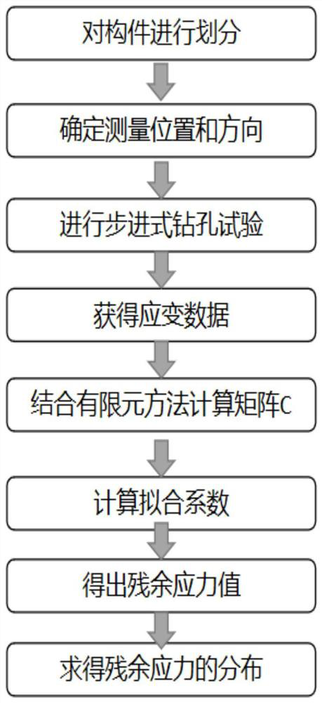
[0044] figure 1 It is a flowchart of the measurement and calculation of the residual stress of the composite material plate; Figure 4 is a schematic diagram of the residual stress measurement of a composite sheet based on the step drilling method.

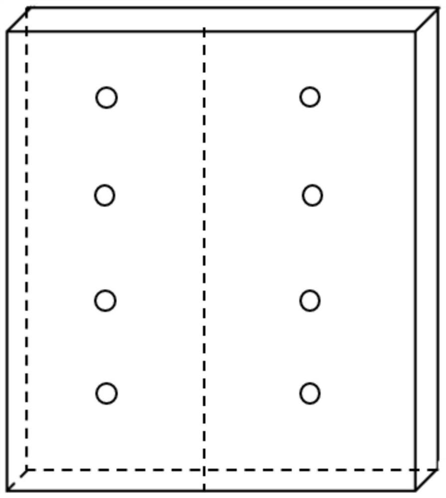
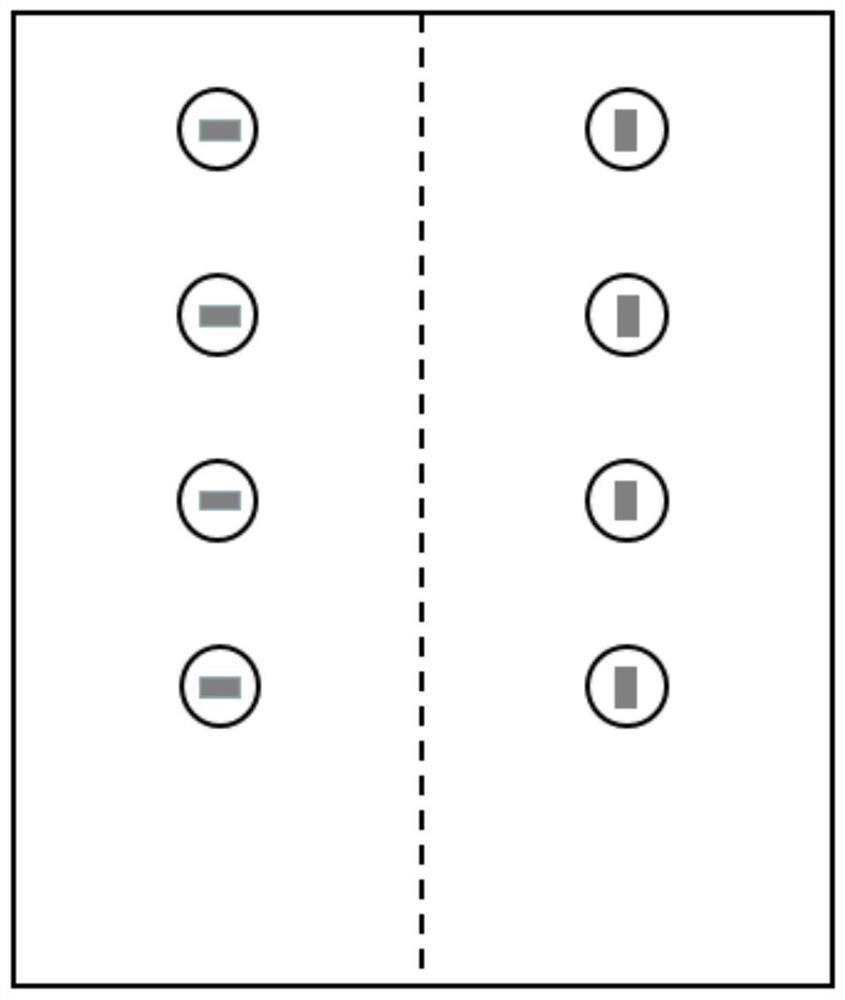
[0045] (1) determine the area to be measured and the direction of the composite material plate 1, figure 2 and image 3 A common test scheme is shown, and 8 drilling positions are determined. The longitudinal stress is measured on one side of the plate and the transverse stress is measured on the other side. In addition, the drilling position and the direction of the strain gauge can be determined by oneself according to the requirements.

[0046](2) Grind the first drilling position I in the area to be tested with fine sandpaper in a direction 45° from the strain g...


PUM


Abstract

The invention belongs to the field of composite material residual stress measurement, and provides a blind hole method based residual stress distribution measurement method for a composite material plate. The method comprises the following steps: firstly, determining a measurement position and a measurement direction for the to-be-measured composite material plate, and adhering a plurality of strain gauges to corresponding positions; using a numerical control drilling machine for conducting stepping drilling on the back face of the position, where the strain gauges are pasted, of the plate, drilling the plate for multiple times with the fixed stepping amount, determining the drilling depth according to the measurement purpose, and after drilling is completed, obtaining strain values, changing along with the drilling depth, measured by the strain gauges at the blind hole positions; then, solving stress distribution at all strain gauge positions by utilizing a finite element model; and finally, correspondingly measuring other directions and position by changing the pasting direction of the strain gauges and the positions of the blind holes.

Description

technical field [0001] The invention belongs to the field of residual stress measurement of composite materials, and relates to a method for measuring residual stress distribution of composite material plates based on a blind hole method. Background technique [0002] During the molding process of the composite material, due to the difference in the thermal expansion coefficient of the fiber and the matrix and the difference in the internal and external cooling rates, obvious residual stress will be generated during the cooling process. The generation of residual stress will cause the plate to warp and deform. There are many adverse effects in the use process. Therefore, in order to achieve the purpose of controlling the residual stress, the measurement of the residual stress of the composite material is particularly critical. At present, the commonly used residual stress measurement methods are mainly divided into two categories: non-destructive testing and destructive tes...

Claims


Application Information

Patent Timeline
IPC IPC(8): G01L5/00G01N19/00
CPCG01L5/0047G01N19/00
Inventor 刘学术张博添
Owner DALIAN UNIV OF TECH
Learn More