
River water sampling device for water conservancy project

A water conservancy project and sampling device technology, which is applied to sampling devices, sampling, measuring devices, etc., can solve problems such as low work efficiency

Inactive Publication Date: 2020-10-30
张传华
View PDF0 Cites 2 Cited by
  • Summary
  • Abstract
  • Description
  • Claims
  • Application Information

AI Technical Summary

Problems solved by technology

[0003] In water conservancy projects, water quality sampling is sometimes required. The existing sampling device can only sample one position at a time, and the work efficiency is low.

Method used


Image

  • River water sampling device for water conservancy project
  • River water sampling device for water conservancy project
  • River water sampling device for water conservancy project

Examples


Embodiment 1

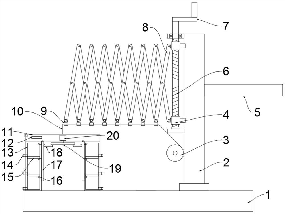
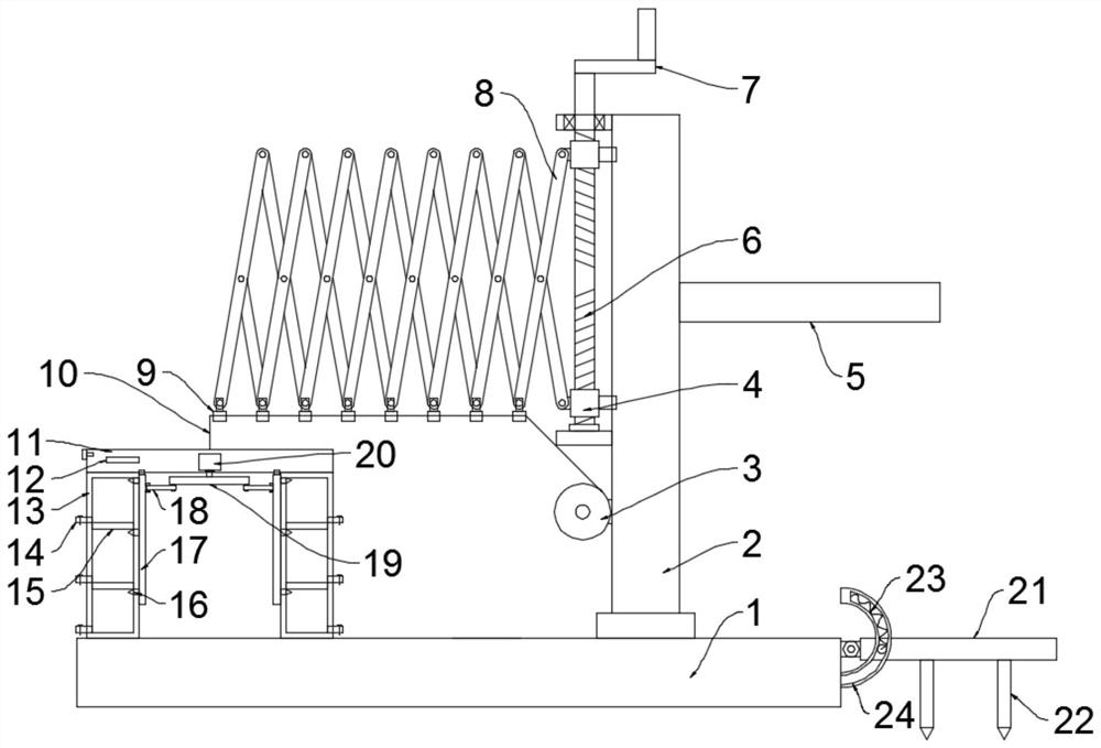
[0023] see figure 1 , in an embodiment of the present invention, a river water sampling device for water conservancy engineering, including a sampling unit, the sampling unit includes a mounting plate 11, a sampling cylinder 13, a motor 20, a turntable 19 and a connecting rod 18, and the lower surface of the mounting plate 11 is A plurality of sampling tubes 13 are fixedly installed at the same distance in the outer ring. In this embodiment, the sampling tubes 13 are preferably fixed to the mounting plate 11 by welding. The wall of the sampling tube 13 is provided with a sampling port. A discharge pipe 14 for discharging sampled water is provided, a valve is installed on the discharge pipe 14, and an installation cavity for installing a motor 20 is provided in the installation plate 11, the output shaft of the motor 20 extends below the installation plate 11 and is fixed with a turntable 19, In this embodiment, the turntable 19 is preferably fixed to the output shaft of the mo...

Embodiment 2

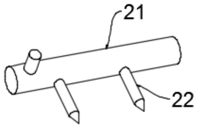
[0028] see Figure 2~3 The difference between this embodiment of the present invention and Embodiment 1 is that a positioning unit is installed on the base plate 1, and the positioning unit includes a mounting rod 21, a drill rod 22 and an arc guide rail 24, and one end of the mounting rod 21 is connected to the base plate 1. Hinged, at least one drill pipe 22 is fixed on the bottom of the installation rod 21, and an arc guide rail 24 is fixed on one side of the installation rod 21 on the base plate 1. The center of the arc guide rail 24 is located at the hinge point of the installation rod 21 and the base plate 1. Rod 21 is fixed with bearing pin near the side wall of arcuate guide rail 24, and arc guide rail 24 is provided with the arc-shaped through groove that inserts for pin shaft, is connected with spring 23 between bearing pin and arc-shaped through groove one end, presses down. The installation rod 21 enables the drill rod 22 to be inserted into the ground, thereby fix...


PUM


Abstract

The invention discloses a river water sampling device for a water conservancy project, relates to the technical field of water conservancy projects, and mainly aims at solving the problem that an existing sampling device can only perform sampling work at one position at a time. The river water sampling device comprises a sampling unit, wherein the sampling unit comprises a mounting plate, a sampling cylinder, a motor, a turntable and a connecting rod. The river water sampling device further comprises a mounting unit used for driving the sampling unit to move, wherein the mounting unit comprises a bottom plate, a mounting column and an adjusting mechanism for adjusting the position of the sampling unit, the adjusting mechanism comprises a bidirectional lead screw, a shear fork structure anda connecting sleeve, the sampling unit is arranged, and a plurality of sampling cylinders can sample a plurality of positions at the same depth at the same time, so that the working efficiency is improved; and the mounting unit is arranged, the sampling direction can be adjusted, the bidirectional lead screw is driven to rotate, the bidirectional lead screw drives an internal thread sleeve to move, the internal thread sleeve drives the shear fork mechanism to stretch out and draw back, and the shear fork mechanism drives the sampling unit to move, so that the position of the sampling unit canbe adjusted, and the sampling range is large.

Description

technical field [0001] The invention relates to the technical field of water conservancy engineering, in particular to a river water sampling device for water conservancy engineering. Background technique [0002] Water conservancy projects are projects built to control and allocate natural surface water and groundwater to achieve the purpose of eliminating harm and rejuvenating profits. Also known as water engineering. Water is an indispensable precious resource for human production and life, but its natural state does not fully meet human needs. Only by building water conservancy projects can we control water flow, prevent floods, and regulate and distribute water to meet the needs of people's life and production for water resources. [0003] In water conservancy projects, water quality sampling is sometimes required. The existing sampling device can only perform sampling at one position at a time, and the working efficiency is low. Contents of the invention [0004] ...

Claims


Application Information

Patent Timeline
IPC IPC(8): G01N1/10
CPCG01N1/10G01N2001/1031
Inventor 张传华
Owner 张传华
Learn More