
Display panel, display panel manufacturing method and display device

A technology for display panels and manufacturing methods, applied in semiconductor/solid-state device manufacturing, electrical components, electric solid-state devices, etc., can solve problems such as poor display effect and impure light emission, and achieve the effect of improving purity and display effect

Inactive Publication Date: 2020-10-30
WUHAN CHINA STAR OPTOELECTRONICS SEMICON DISPLAY TECH CO LTD
View PDF4 Cites 2 Cited by
  • Summary
  • Abstract
  • Description
  • Claims
  • Application Information

AI Technical Summary

Problems solved by technology

[0004] Based on this, it is necessary to provide a display panel, a method for manufacturing a display panel, and a display device for the problems of impure light emission and poor display effect caused by the lateral leakage of holes in the traditional OLED panel.

Method used


Image

  • Display panel, display panel manufacturing method and display device
  • Display panel, display panel manufacturing method and display device
  • Display panel, display panel manufacturing method and display device

Examples


Embodiment Construction

[0037] In order to facilitate the understanding of the present application, the present application will be described more fully below with reference to the relevant drawings. A preferred embodiment of the application is shown in the drawings. However, the present application can be embodied in many different forms and is not limited to the embodiments described herein. On the contrary, the purpose of providing these embodiments is to make the disclosure of this application more thorough and comprehensive.

[0038] It should be noted that when an element is considered to be "connected" to another element, it may be directly connected to and integrally integrated with the other element, or there may be an intervening element at the same time. The term "insert" and similar expressions are used herein for the purpose of illustration only.

[0039] Unless otherwise defined, all technical and scientific terms used herein have the same meaning as commonly understood by one of ordi...


PUM


Abstract

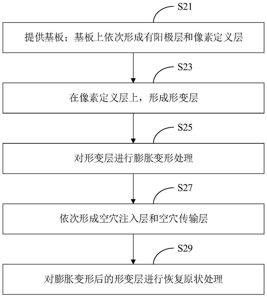
The invention relates to a display panel, a display panel manufacturing method and a display device. The display panel comprises a deformation layer; the deformation layer is a material layer formed by a material which can expand and deform and can restore to the original shape, the deformation layer is clamped between a pixel definition layer and a hole injection layer of the display panel; the deformation layer is used for disconnecting the hole injection layer of the display panel and a hole transmission layer in the manufacturing process of the display panel. The hole injection layer and the hole transmission layer are disconnected by utilizing the deformation layer in the manufacturing process of the display panel, so that hole transverse flowing is prevented to form transverse leakage current, the pixel light-emitting purity is improved, and the display effect is improved.

Description

technical field [0001] The present application relates to the field of display technology, in particular to a display panel, a method for manufacturing a display panel, and a display device. Background technique [0002] OLED (Organic Light-Emitting Diode, Organic Light-Emitting Diode) panel has many advantages such as thinness and low power consumption, and has gradually become the current mainstream display technology. Usually, an OLED panel includes an anode layer, a hole injection layer, a hole transport layer, and a light-emitting layer. , electron transport layer, electron injection layer, cathode layer. [0003] The working principle of the OLED panel is that the anode layer emits holes under the action of an electric field, the holes pass through the hole injection layer, the hole transport layer is transported to the light-emitting layer, the cathode layer emits electrons under the action of the electric field, and the electrons pass through the electron injection l...

Claims


Application Information

Patent Timeline
Patent Type & Authority Applications(China)
IPC IPC(8): H01L51/50H01L51/56H01L27/32
CPCH10K59/10H10K50/15H10K50/17H10K71/00
Inventor 潘杰
Owner WUHAN CHINA STAR OPTOELECTRONICS SEMICON DISPLAY TECH CO LTD
Learn More