
Battery cell manufacturing system and method

A technology for manufacturing systems and cells, applied in secondary battery manufacturing, electrolyte battery manufacturing, final product manufacturing, etc., can solve the problems of low precision, high precision requirements, and high defective cell rate

Pending Publication Date: 2020-10-30
惠州市华维机电设备有限公司
View PDF0 Cites 2 Cited by
  • Summary
  • Abstract
  • Description
  • Claims
  • Application Information

AI Technical Summary

Problems solved by technology

Between the station corresponding to the fine sealing operation and the station corresponding to the edge trimming mechanism, the battery cell is picked and placed by the manipulator. Since the accuracy of placing the battery cell in the station corresponding to the edge trimming mechanism is low, the battery cell is placed in the position corresponding to the edge trimming mechanism. The edge trimming accuracy of the edge trimming mechanism is low. In addition, after the edge trimming mechanism, the cells need to be transported to the folding station for this operation. This requires high precision for the manipulator to place the cells on the edge trimming mechanism, resulting in The defective rate of cell processing is high; in addition, there is no inspection process during the entire processing of the cell, and some cells may already be defective before being processed by the trimming mechanism, and the entire processing process of the cell is still completed , so that the production efficiency of the cell is low

Method used


Image

  • Battery cell manufacturing system and method
  • Battery cell manufacturing system and method
  • Battery cell manufacturing system and method

Examples


Embodiment Construction

[0012] In order to facilitate the understanding of the present invention, the present invention will be described more fully below with reference to the associated drawings. Preferred embodiments of the invention are shown in the accompanying drawings. However, the present invention can be embodied in many different forms and is not limited to the embodiments described herein. On the contrary, the purpose of providing these embodiments is to make the disclosure of the present invention more thorough and comprehensive. It should be noted that when an element is referred to as being “fixed” to another element, it can be directly on the other element or there can also be an intervening element. When an element is referred to as being "connected to" another element, it can be directly connected to the other element or intervening elements may also be present. The terms "vertical," "horizontal," "left," "right," and similar expressions are used herein for purposes of illustration...


PUM


Abstract

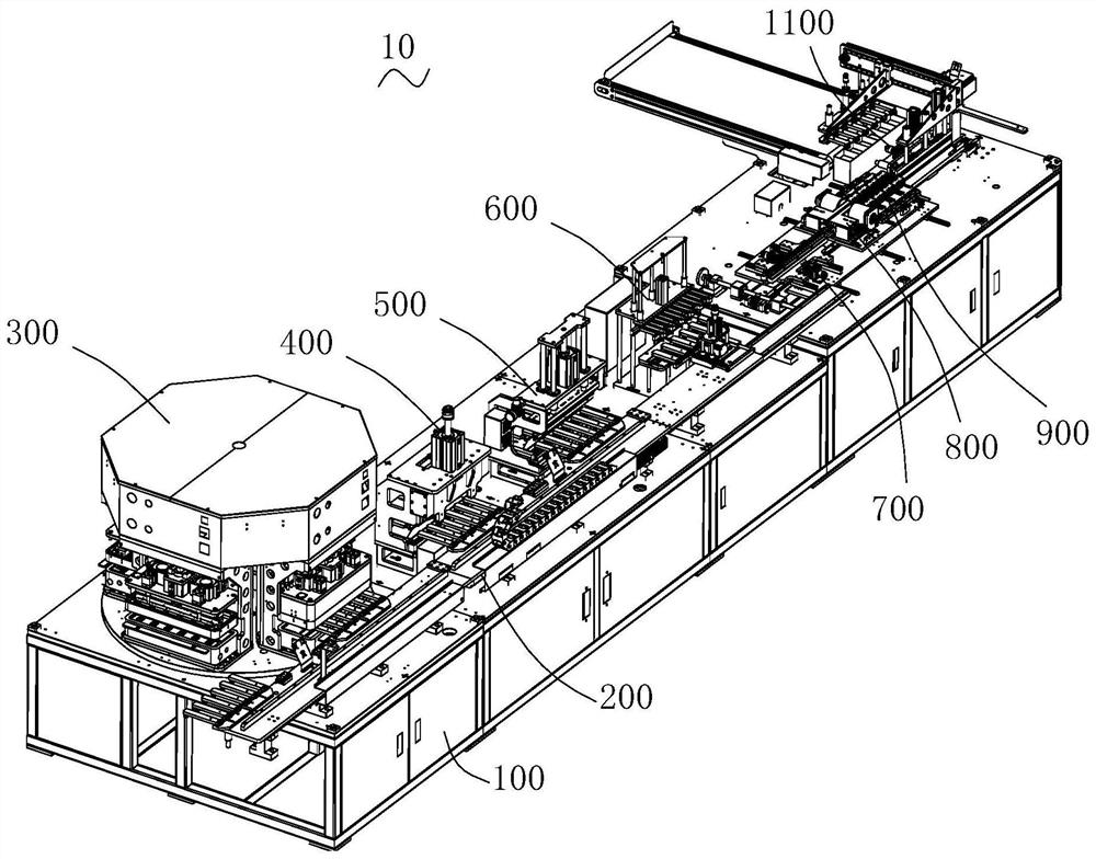
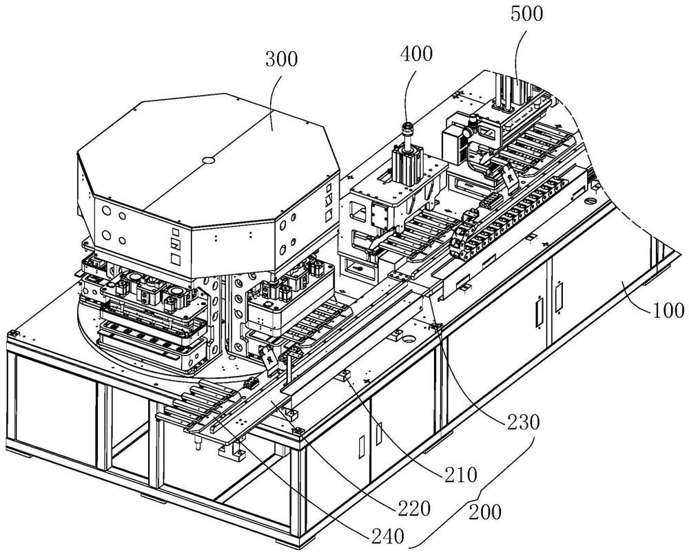
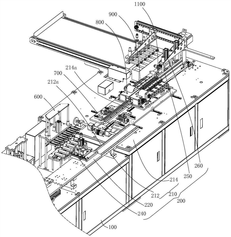
The invention provides a battery cell manufacturing system and method. The battery cell manufacturing system comprises a rack, a conveying device arranged on the rack, and a vacuumizing packaging device, a cutting mechanism, a fine sealing mechanism, a voltage measuring mechanism, a positioning mechanism, an edge cutting mechanism, a double-edge folding mechanism and a heat sealing mechanism whichare sequentially arranged on the rack in the conveying direction of the conveying device, wherein the conveying device is used for sequentially conveying the battery cell to the vacuumizing packagingdevice, the cutting mechanism, the fine sealing mechanism, the voltage measuring mechanism, the positioning mechanism, the edge cutting mechanism, the double-edge folding mechanism and the heat sealing mechanism, the vacuumizing packaging device is used for carrying out vacuum packaging of the battery cell, and the voltage measuring mechanism is used for measuring the voltage of the finely sealedbattery cell. According to the battery cell manufacturing system, the situation that unqualified battery cells are continuously machined on stations corresponding to the positioning mechanism, the edge cutting mechanism, the double-edge-folding mechanism and the heat sealing mechanism, and consequently machining efficiency of the qualified battery cells is wasted is avoided, and a problem that the production efficiency of the battery cells is low is solved.

Description

technical field [0001] The invention relates to the technical field of electric core manufacturing, in particular to a battery manufacturing system and method. Background technique [0002] The cell processing process includes initial positioning, vacuum packaging, material cutting, edge ironing, edge trimming, bending, and edge ironing. Due to the poisonous and harmful substances contained in the battery cell, the lithium battery needs to be packaged after the liquid injection process is completed. The generated gas is extracted, and then the aluminum-plastic film is heated and pressurized in a vacuum environment to realize the vacuum packaging of the battery cell, so as to prevent the lithium battery from leaking when it is put on the market. [0003] The traditional cell manufacturing system performs material cutting and fine sealing operations sequentially after the vacuum packaging operation to achieve fine sealing of the cells, and then the manipulator picks and place...

Claims


Application Information

Patent Timeline
IPC IPC(8): H01M10/04H01M10/058
CPCH01M10/0404H01M10/058Y02E60/10Y02P70/50
Inventor 何勇王勇军邓江帆程红科贺军
Owner 惠州市华维机电设备有限公司
Learn More