Rotor core and steam turbine generator with rotor core

A steam turbine generator and rotor core technology, which is applied to machines/engines, electrical components, electromechanical devices, etc., can solve problems affecting work efficiency, operation safety, magnetic circuit loss, and aging of rotor core surface insulation, so as to improve heat dissipation capacity. And the effect of heat dissipation uniformity and prolonging service life

Pending Publication Date: 2020-10-30
广州广重企业集团有限公司
View PDF0 Cites 0 Cited by
  • Summary
  • Abstract
  • Description
  • Claims
  • Application Information

AI Technical Summary

Problems solved by technology

In the existing rotor core 101, the center line 104 between the side walls of the opposite slots 103 on two adjacent rotor punches 102 is the same distance from the side walls of the rotor punches 102 on both sides, so that a single rotor punch The sheet 102 itself forms a symmetrical structure. After the multiple rotor cores 101 are laminated and connected in the axial direction, the side walls of the multiple rotor punching sheets 102 in the same row are butted to form a side plane, and the wires are wound on the side plane. When on, there is no heat dissipation gap between the wire and the side plane, such as figure 1 As shown, when the turbogenerator is in operation, the internal rotor core will generate magnetic circuit loss and heat loss, and these losses will be converted into heat energy, which will increase the temperature of the turbogenerator, and if the temperature is too high, the surface of the rotor core will Insulation aging, which affects its working efficiency and operational safety

Method used


Image

  • Rotor core and steam turbine generator with rotor core
  • Rotor core and steam turbine generator with rotor core
  • Rotor core and steam turbine generator with rotor core

Examples


Embodiment Construction

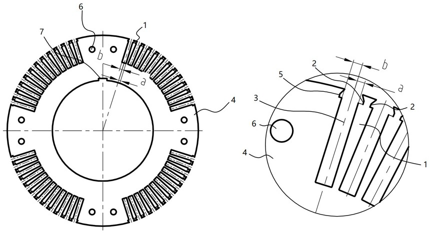
[0013] A rotor core, such as figure 2 As shown, it includes a plurality of rotor punches 1 arranged at intervals, the two opposite side walls on the free end side of the rotor punches 1 are respectively provided with first grooves 2, and two adjacent rotor punches 1 The distance between the center line 3 between the side walls of the opposite first groove body 2 is a from the side wall of the rotor punch 1 on one side, and the distance from the side wall of the rotor punch 1 on the other side is b, and b>a or b figure 2 As shown, the distance between the center line 3 between the opposite side walls of the first slot body 2 on two adjacent rotor punches 1 is c from the side wall of the first slot body 2 . Wherein, the values ​​of a and b are calculated and determined according to the actual magnetic circuit, and the calculation method is the prior art.

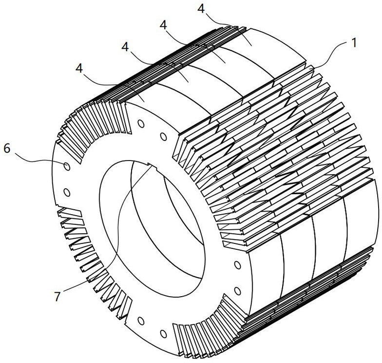
[0014] The rotor core 4 includes a ring-shaped body on which a plurality of sets of rotor punching sets are arranged at in...


PUM


Abstract

The invention discloses a rotor core and a steam turbine generator with the rotor core. A concave-convex surface is formed on the side wall surface formed by connecting rotor punching sheets in the same row; the distance between the concave surface and the convex surface is the difference between the distance b and the distance a; and after a wire is embedded on the side walls of the rotor punching sheets, a gap is formed between the line and the concave surface, and the gap is a heat dissipation space of the rotor core, so that on the premise of ensuring the magnetic circuit and the strengthof the rotor core, the heat dissipation capacity and the heat dissipation uniformity of the rotor core are greatly improved, the influence of large local temperature difference of the rotor core on the operation efficiency of the steam turbine generator is avoided, the stable operation of the rotor core and the steam turbine generator with the rotor core is ensured, and the service life of the steam turbine generator is greatly prolonged.

Description

technical field [0001] The present invention relates to a rotor core and a turbogenerator with the rotor core. Background technique [0002] The rotor core is one of the key components of the turbogenerator. It is a part of the magnetic circuit and has good magnetic permeability. It is also one of the main parts that cause the temperature rise of the turbogenerator. In the existing rotor core 101, the center line 104 between the side walls of the opposite slots 103 on two adjacent rotor punches 102 is the same distance from the side walls of the rotor punches 102 on both sides, so that a single rotor punch The sheet 102 itself forms a symmetrical structure. After the multiple rotor cores 101 are laminated and connected in the axial direction, the side walls of the multiple rotor punching sheets 102 in the same row are butted to form a side plane, and the wires are wound on the side plane. When on, there is no heat dissipation gap between the wire and the side plane, such as...

Claims


Application Information

Patent Timeline
Patent Type & Authority Applications(China)
IPC IPC(8): H02K1/22H02K1/28H02K1/32F01D15/10
CPCF01D15/10H02K1/22H02K1/28H02K1/32H02K2213/03
Inventor 黄冠豪鲜青龙黎瑞涛吴俊濠杨骏
Owner 广州广重企业集团有限公司
Why Eureka
Try Eureka