
Iron core structure, rotor assembly, motor and compressor

An iron core structure and iron core technology, which is applied in the fields of iron core structure, rotor assembly, motor and compressor, can solve the problems of affecting efficiency and electromagnetic noise, too large stator and rotor air gap, and large motor torque loss, etc. Noise of the whole machine, reduction of harmonic content, and effect of reducing the amplitude of electromagnetic force

Pending Publication Date: 2020-10-30
ZHUHAI GREE REFRIGERATION TECH CENT OF ENERGY SAVING & ENVIRONMENTAL PROTECTION
View PDF0 Cites 2 Cited by
  • Summary
  • Abstract
  • Description
  • Claims
  • Application Information

AI Technical Summary

Problems solved by technology

In the prior art, a rotor core composed of multiple arcs is used in the rotor structure, including multiple inclined slits on the outside of the magnetic steel slot to improve the iron loss of the armature and reduce electromagnetic noise. The outer surface of the rotor is composed of multiple arcs. Different arc radius size settings will easily cause the air gap between the stator and rotor to be too large, the motor torque loss will be large, the motor output will become smaller, and the motor efficiency will rapidly decay under large torque loads
At the same time, the inclined slit structure forms a certain angle with the permanent magnet, and the slit width in the magnetization direction of the permanent magnet has a certain hindering effect on the flux linkage, resulting in a reduction of the motor flux linkage, affecting efficiency and electromagnetic noise

Method used


Image

  • Iron core structure, rotor assembly, motor and compressor
  • Iron core structure, rotor assembly, motor and compressor
  • Iron core structure, rotor assembly, motor and compressor

Examples


Embodiment Construction

[0062] In order to make the purpose, technical solution and advantages of the present invention clearer, the technical solution of the present invention will be clearly and completely described below in conjunction with specific embodiments of the present invention and corresponding drawings. Apparently, the described embodiments are only some of the embodiments of the present invention, but not all of them. Based on the embodiments of the present invention, all other embodiments obtained by persons of ordinary skill in the art without making creative efforts belong to the protection scope of the present invention.

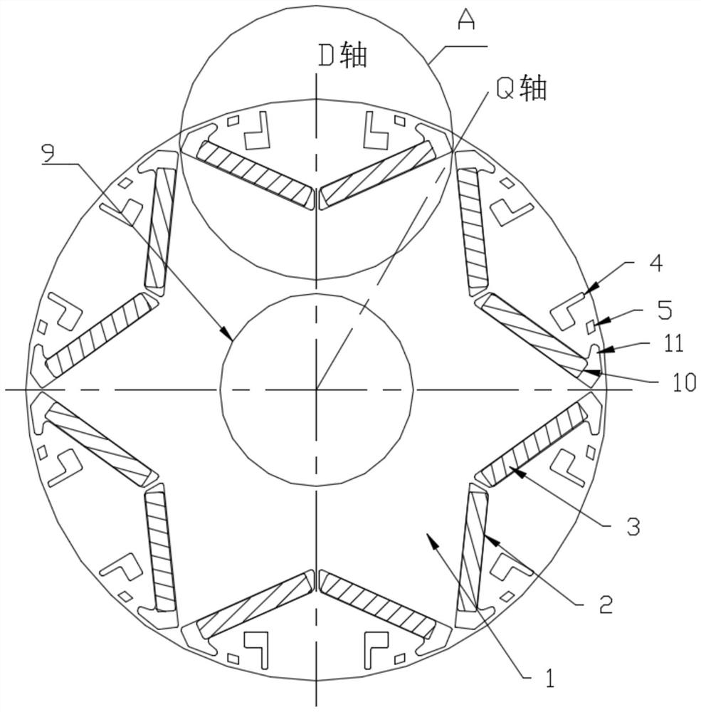
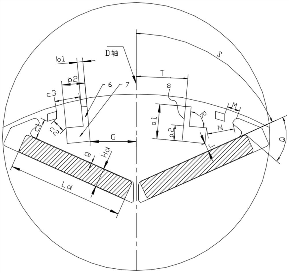
[0063] combine Figure 1 to Figure 6As shown, this embodiment provides an iron core structure, including: an iron core body 1; a plurality of sets of magnetic steel grooves 2 uniformly distributed along the circumferential direction of the iron core body 1 and used to accommodate permanent magnets 3, and magnetic steel grooves 3 The N and S poles of the permanent...


PUM


Abstract

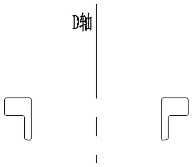
The invention provides an iron core structure, a rotor assembly, a motor and a compressor. The iron core structure comprises an iron core body; the plurality of groups of magnetic steel grooves are uniformly distributed along the circumferential direction of the iron core body and are used for accommodating the permanent magnets; first magnetism isolating holes are formed between the magnetic steel grooves and the outer circumference of the iron core body, the ends, away from the D axis, of the magnetic steel grooves are first end parts, and the first magnetism isolating holes are adjacent tothe first end parts; the first magnetic isolation holes are L-shaped, and one edge of the L shape is arranged along the radial direction of the iron core body. According to the iron core structure, the L-shaped first magnetic isolation holes are formed in the two ends, away from the D axis, of one magnetic pole respectively, so that a motor magnetic circuit is optimized and the electromagnetic force amplitude of the rotor iron core is reduced under the condition that the output torque of the motor is not influenced. The harmonic content in the air gap flux density can be reduced, the iron lossof the motor is further reduced, and the vibration noise of the motor is improved, so that the overall noise of the compressor is reduced.

Description

technical field [0001] The invention belongs to the technical field of motors, and in particular relates to an iron core structure, a rotor assembly, a motor and a compressor. Background technique [0002] As the core component of the compressor, the efficiency and noise of the motor directly affect the overall performance of the compressor. In the prior art, a rotor core composed of multiple arcs is used in the rotor structure, including multiple inclined slits on the outside of the magnetic steel slot to improve the iron loss of the armature and reduce electromagnetic noise. The outer surface of the rotor is composed of multiple arcs. Different arc radius size settings will easily cause the air gap between the stator and rotor to be too large, the motor torque loss will be large, the motor output will become smaller, and the motor efficiency will decay rapidly under a large torque load. At the same time, the inclined slit structure forms a certain angle with the permanent...

Claims


Application Information

Patent Timeline
Patent Type & Authority Applications(China)
IPC IPC(8): H02K1/27H02K1/32
CPCH02K1/276H02K1/32
Inventor 赵素珍王晶孙文娇陈华杰周博耿高旭
Owner ZHUHAI GREE REFRIGERATION TECH CENT OF ENERGY SAVING & ENVIRONMENTAL PROTECTION
Learn More