
Miniature portable protective clothing refrigerating system

A refrigeration system and protective clothing technology, applied in protective clothing, protective devices against harmful chemicals, clothing, etc., can solve the problems of loss of refrigeration function, low refrigeration efficiency, affecting comfort, etc., and reduce the overall size and weight. , High cooling efficiency, good heat dissipation effect

Pending Publication Date: 2020-11-03
焦永生
View PDF1 Cites 0 Cited by
  • Summary
  • Abstract
  • Description
  • Claims
  • Application Information

AI Technical Summary

Problems solved by technology

[0004] However, although semiconductor refrigerating sheets have the advantage of fast cooling speed, they also have the following disadvantages: 1) The refrigerating efficiency of semiconductor refrigerating sheets is low, and its cooling efficiency is about 0.6, which is fixed and cannot be changed by technical means, making it difficult to timely , Fully take away the heat in the protective clothing, if you need to increase the cooling capacity, you need to increase the semiconductor cooling sheet, which will increase the quality and volume of the cooling system, which is not conducive to wearing
2) The low cooling efficiency requires a large-capacity DC power supply, which makes it unable to work for a long time. At the same time, it also releases a large amount of heat to the working environment, which affects the surrounding thermal environment. Moreover, the larger the capacity of the DC power supply, its quality and volume It is also larger, making it bulky to wear and affecting comfort
3) The semiconductor refrigeration sheet cannot withstand vibration, even if it falls from a height of 20-30cm, it will lose its refrigeration function

Method used


Image

  • Miniature portable protective clothing refrigerating system
  • Miniature portable protective clothing refrigerating system
  • Miniature portable protective clothing refrigerating system

Examples


Embodiment Construction

[0024] The technical solution of the present invention will be described in further non-limiting detail below in combination with preferred embodiments and accompanying drawings.

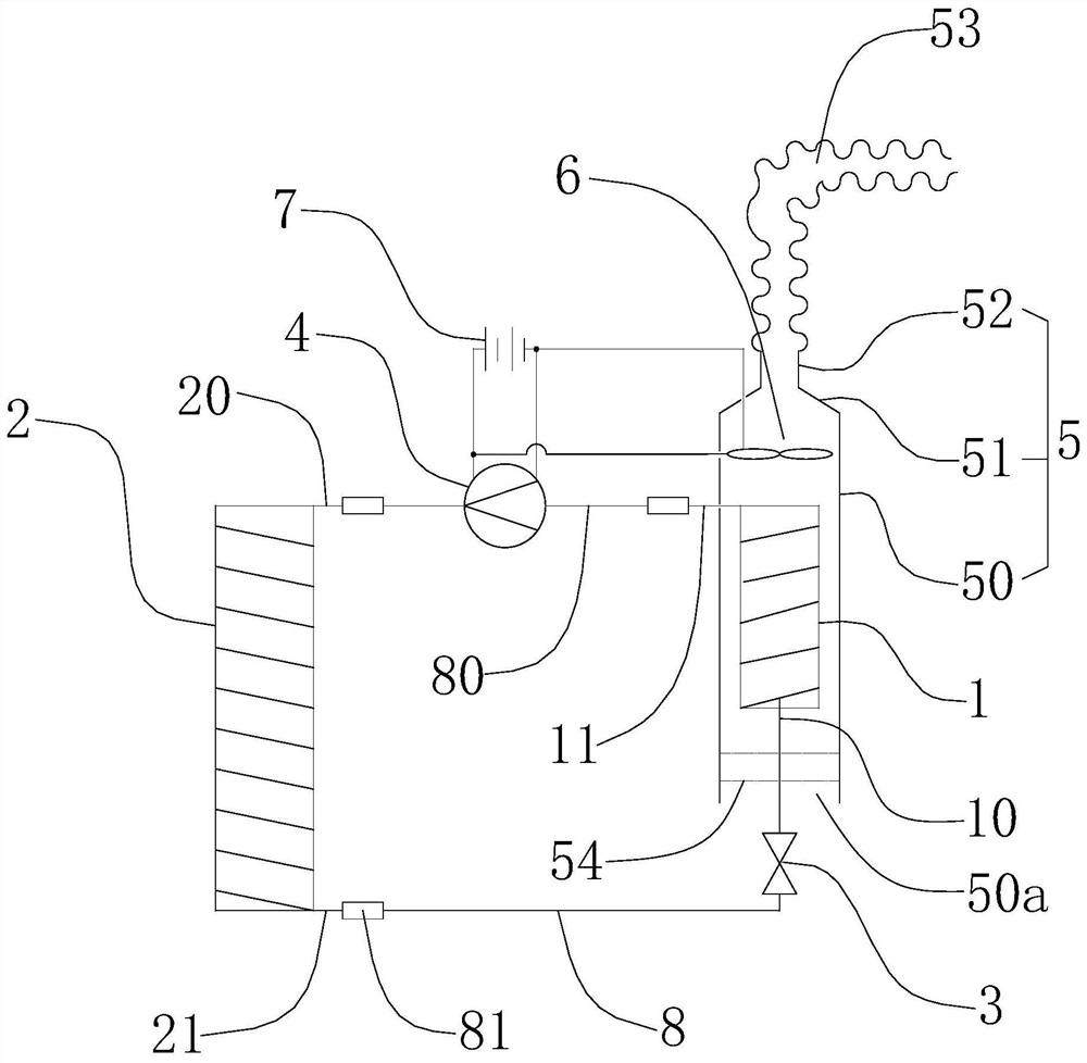
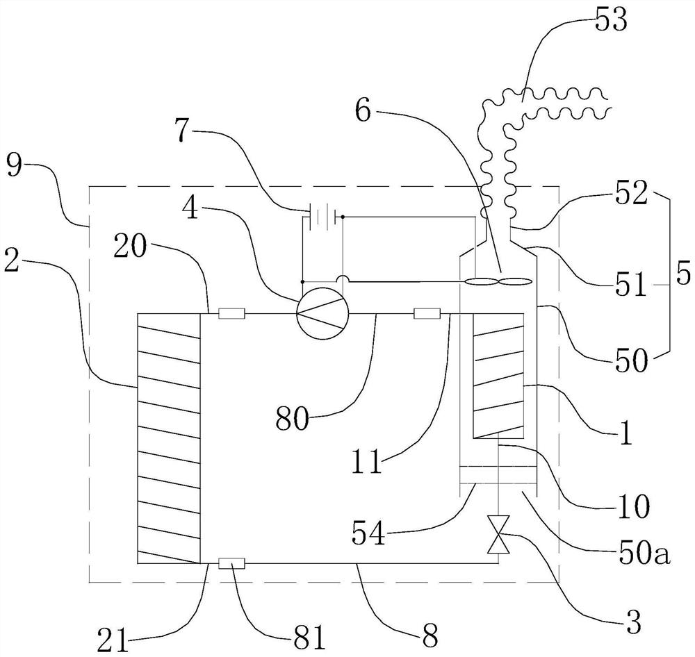
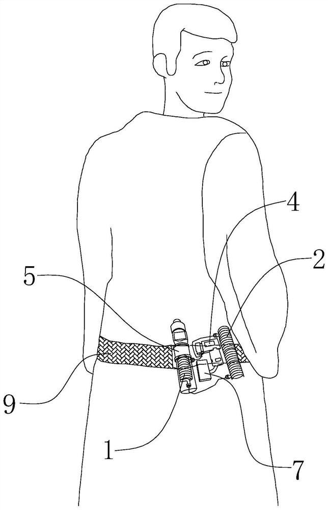
[0025] Such as figure 1 Shown, correspond to the miniature portable protective clothing cooling system of a kind of preferred embodiment of the present invention, and it comprises evaporator 1, condenser 2, throttling device 3, vacuum pump 4, gathering wind shell 5, blower fan 6 and power supply 7.

[0026] The evaporator 1, the condenser 2, the throttling device 3 and the vacuum pump 4 are connected to form a closed loop through pipelines. Specifically, the evaporator 1 includes a first inlet 10 and a first outlet 11, and the condenser 2 includes a second inlet 20 and the second outlet 21, the throttling device 3 is installed on the first pipeline 8 connected between the first inlet 10 and the second outlet 21, and the vacuum pump 4 is installed between the second inlet 20 and the first outlet 11 ...


PUM


Abstract

The invention discloses a miniature portable protective clothing refrigerating system which comprises an evaporator, a condenser, a throttling device, a vacuum pump, a wind gathering shell, a fan anda power supply. The evaporator, the condenser, the throttling device and the vacuum pump are connected through pipelines, and the miniature portable protective clothing refrigerating system further comprises a refrigerant arranged in the pipelines. The refrigerant is driven by the vacuum pump to circularly flow among the condenser, the throttling device and the evaporator in sequence, the fan is arranged in a manner of corresponding to the evaporator and used for blowing cold air around the evaporator into protective clothing, and the power supply is used for supplying power to the vacuum pumpand the fan. According to the miniature portable protective clothing refrigeration system, refrigeration is conducted through phase state changes of the refrigerant, the refrigeration efficiency is higher, the cooling capacity needed by human body heat dissipation can be effectively provided, heat dissipated from the human body is rapidly absorbed, and the protective clothing is more cool and comfortable to wear.

Description

technical field [0001] The invention relates to a miniature portable protective clothing refrigeration system. Background technique [0002] At present, it is necessary to wear airtight protective clothing in many occasions. For example, in workshops or hospitals with high dust-proof requirements, it is often required to wear airtight protective clothing, especially in the process of epidemic prevention, the wearing of protective clothing is even more unavoidable. lack. [0003] Due to the good airtightness of protective clothing, it is easy to feel stuffy when wearing it. Improving its ventilation performance is particularly important for wearing comfort. In the prior art, protective clothing equipped with a refrigeration system already exists. For example, the Chinese invention patent with the application number 201920873900.5 discloses a double-layer refrigeration air-conditioning clothing, which includes semiconductor cooling chips (also known as thermoelectric cooling ...

Claims


Application Information

Patent Timeline
Patent Type & Authority Applications(China)
IPC IPC(8): A62B17/00A41D13/005A41D27/00
CPCA41D13/0053A41D27/00A62B17/005
Inventor 焦永生
Owner 焦永生
Learn More