Automatic production equipment for internal cover plates

A technology for production equipment and cover plates, applied in metal processing equipment, feeding devices, forming tools, etc., can solve the problems of low production efficiency, insufficient completeness, accumulation of cocoons, soaking and cooking, etc., to achieve automatic production and improve production efficiency and yield effect

Inactive Publication Date: 2020-11-03
HEFEI ZHIDE IND & TRADE
9 Cites 0 Cited by

AI-Extracted Technical Summary

Problems solved by technology

[0003] The object of the present invention is to provide an automatic production equipment for internal cover boards. The problem it aims to solve is: the existing method of cocoon cook...

Method used

Further scheme is: each stamping device 10 is arranged at intervals in a row, and conveying line 20 comprises the walking guide rail that is positioned at the setting of each stamping device 10 front ends, and walking guide rail is fixedly assembled on the guide rail support, and transfer mechanism 30 is slidably installed on the walking guide rail. On the guide rail, the material transfer mechanism is set at intervals, which can improve production efficiency.
The conveying guide roller that feeding conveying unit is arranged at intervals constitutes, and oiling mechanism 43 is arranged on the delivery path of feeding conveying unit, and oiling mechanism 43 is made of the oiling roller that arranges up and down, and the surface of oiling roller A felt layer for absorbing oil is arranged, and the surface of the sheet material is oiled when the sheet material passes between two oiling rollers. The upper side oiling roller is movable and installed, the side of the upper oiling roller is also provided with a spray pipe, the lower side of the oiling mechanism 43 is provided with an oil recovery tank, and the front and rear sides of the oiling mechanism 43 are provided with a material The A and B sensors for detection, and the C sensor are installed at the end of the feeding and conveying unit to realize reliable oiling treatment of sheet metal parts.
The material transfer frame 317 comprises two material transfer mounting parts arranged parallel to each other, the length direction of the material transfer mounting part is consistent with the length direction of the walking slide rail, and the two sucker mounting arms 331 at the two ends of the charging mounting part are in the shape of "<" type arrangement with the jaws of the mounting arm pointing to the outside of the transfer mount. An electromagnet assembly is also arranged on the transfer rack 317 . The electromagnet assembly is arranged in the middle of the transfer frame 317, and the transfer sucker 332 is arranged on the outer periphery of the electromagnet assembly. Improve the reliability of the suction of sheet metal parts, and at the same time facilitate the unloading of waste materials after stamping.
The present invention provides a kind of automatic production equipment of interior cover plate, comprises the conveying line 20 that is used to realize plate material conveying, and the conveying path of conveying line 20 is provided with the stamping device 10 that is used to realize plate material forming at intervals A material transfer mechanism 30 is provided between adjacent punching devices 10, a feeding mechanism 40 for supplying plate materials is provided at the head end of the conveying line 20, and a feeding mechanism 40 for supplying the formed product is provided at the tail end of the conveying line 20. Unloading device for unloading. The present invention is an improvement made on the basis of the existing embodiment of manual material transfer, so the implementation of the stamping device 10 remains consistent with the existing ones. By adding the conveying lin...

Abstract

The invention relates to automatic production equipment for internal cover plates. The automatic production equipment comprises a conveying line for conveying plate materials, stamping devices for forming the plate materials are arranged on a conveying path of the conveying line at intervals, and a material transfer mechanism is arranged between every two adjacent stamping devices; and a feeding mechanism used for supplying the plate materials is arranged at the head end of the conveying line, and a discharging device used for discharging the formed products is arranged at the tail end of theconveying line. According to the automatic production equipment, an improvement is made on the basis of an existing manual material transferring implementation scheme, and therefore implementation ofthe stamping devices is kept consistent with that of existing stamping devices. By additionally arranging the conveying line, the transfer mechanism, the feeding device and the like, automatic production of the cover plates is achieved, and the production efficiency and the yield are improved.

Application Domain

Technology Topic

Image

  • Automatic production equipment for internal cover plates
  • Automatic production equipment for internal cover plates
  • Automatic production equipment for internal cover plates

Examples

  • Experimental program(1)

Example Embodiment

[0039] In order to make the objectives and advantages of the present invention clearer, the present invention will be specifically described below in conjunction with embodiments. It should be understood that the following text is only used to describe one or several specific embodiments of the present invention, and does not strictly limit the protection scope of the specific claim of the present invention.
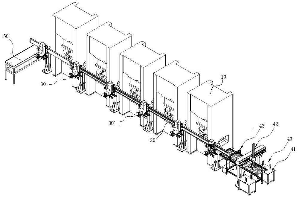
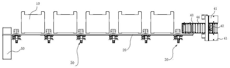
[0040] The present invention provides an automatic production equipment for an inner cover plate, which includes a conveying line 20 for conveying sheet materials. The conveying path of the conveying line 20 is provided with a punching device 10 for forming sheet materials at intervals. A material transfer mechanism 30 is provided between the stamping devices 10, a feeding mechanism 40 for supplying sheet materials is provided at the head end of the conveying line 20, and a feeding mechanism 40 is provided at the end of the conveying line 20 for discharging the formed product. The unloading device. The present invention is an improvement based on the existing implementation of manual material transfer, so the implementation of the punching device 10 is consistent with the existing implementation. By adding the conveyor line 20, the transfer mechanism 30, the feeding device, etc., the automatic production of the cover plate is realized, and the production efficiency and the yield rate are improved.
[0041] A further solution is: each punching device 10 is arranged at intervals in a row, the conveying line 20 includes a walking rail set at the front end of each punching device 10, the walking rail is fixedly assembled on the guide rail bracket, and the transfer mechanism 30 is slidably installed on the walking rail. The material transfer mechanism set at intervals can improve production efficiency.
[0042] An oiling mechanism 43 for applying oil to the sheet material is provided between the feeding device and the adjacent transfer mechanism 30. Apply oil to the plate to avoid damage during the processing of the plate. The feeding mechanism 40 includes a stacking unit 41 for stacking circular sheet materials, a reclaiming unit 42 for fetching the sheet materials, and a feeding and conveying unit for conveying the sheet materials. The feeding mechanism is used for sucking and placing the sheet material on the stacking unit 41 on the feeding and conveying unit. Two stacking units 41 are provided. The two stacking units 41 are separately placed on the two outer sides of the feeding and conveying unit. The reclaiming unit 42 includes a horizontally arranged reclaiming rail 421. The length of the reclaiming rail 421 and the two stacking units 41. The length direction between 41 is consistent. The reclaiming guide 421 is provided with a reclaiming slide 422 that is slidingly matched with it. The reclaiming slide 422 is connected with the horizontal reclaiming adjustment assembly that drives it to move. A reclaimer 423 slidably installed in the vertical direction is provided. The reclaimer 422 is provided with a vertical reclaiming adjustment assembly that adjusts the vertical movement of the reclaimer 423 to connect. The lower end of the reclaimer 423 is provided with a suction plate. Piece reclaiming suction cup 426. The implementation of the above scheme improves production efficiency and avoids downtime caused by intermittent feeding.
[0043] The feeding and conveying unit is composed of conveying guide rollers arranged at intervals. The oiling mechanism 43 is arranged on the conveying path of the feeding and conveying unit. The oiling mechanism 43 is composed of upper and lower oiling rollers. The surface of the oiling roller is provided with adsorption The felt layer of oil fluid coats the surface of the sheet material when the sheet material passes between two oiling rollers. The upper oiling roller can be moved up and down. A spray pipe is also provided on the side of the upper oiling roller. The oil recovery tank is provided on the lower side of the oiling mechanism 43, and the front and rear sides of the oiling mechanism 43 are provided with materials. The A and B sensors for detection, and the C sensor is installed at the end of the feeding and conveying unit to realize reliable oiling treatment for the sheet material.
[0044] The stacking unit 41 includes a pallet, and the periphery of the pallet is provided with a stopper positioning rod and a detection sensor that detects the amount of remaining material on the stripping table. There is also a two-piece detection mechanism that detects the number of sheet materials taken in a single time on the reclaiming rack 423. The two-piece detection mechanism is connected to the control unit, and the control unit regulates the operation of each mechanism according to the signal detected by the two-piece detection mechanism. Operating status. The double-chip detection sensor is composed of two sheet material sensors arranged correspondingly up and down, and the double-chip detection sensor is arranged on the moving path of the reclaimer 423 after reclaiming the material. Avoid wrong picking and ensure the reliability of picking.
[0045] The feeding and conveying unit is also provided with a correction mechanism for correcting the posture of the sheet material, and the correction mechanism includes a correction plate movably installed along the length of the conveying guide roller. Ensure that the position of each reclaiming is fixed and improve the accuracy of feeding.
[0046] The reclaiming rack 423 includes a horizontally arranged reclaiming lifting plate 424. The reclaiming lifting plate 424 is slidably mounted on the reclaiming slide 422 through a reclaiming guide rod. The reclaiming slide 422 is provided with a reclaiming lifting plate 424. The reclaiming cylinder moves up and down. The lower surface of the reclaiming lifting plate 424 is provided with two reclaiming installation beams arranged in parallel. The reclaiming installation beams are provided with reclaiming installation arms for installing the reclaiming suction cup 426 at intervals. A strip hole is opened at one end of the material mounting arm. The length of the hole of the A strip hole is consistent with the length of the reclaiming installation arm. The reclaiming installation beam is provided with an A bolt that matches the A strip hole, and the reclaiming suction cup 426 is floating mounted on the other end of the reclaiming arm.
[0047] The transfer mechanism 30 includes a material transfer slide 311 slidably mounted on the walking rail. The material transfer slide 311 is connected with an A1 material transfer adjustment assembly that drives it to move along the length of the walking rail. The material transfer slide 311 is provided with A lifting installation part that is vertically installed in a vertical direction. The lifting installation part is connected with the B1 adjustment assembly that adjusts it for lifting. The lifting installation part is provided with a transfer mounting frame that is slidably installed in the direction A, and the direction A is for walking In the horizontal direction where the guide rails are arranged in an intersecting manner, the transfer mounting frame is connected with the A3 transfer adjustment assembly that adjusts its movement in the direction A. The transfer mounting frame is provided with a transfer frame 317, and the transfer frame 317 is installed with a suction plate Material transfer sucker 332 assembly. Realize the reliable demand for sheet material transfer and reclaim.
[0048] The material transfer suction cup 332 assembly includes a material transfer suction cup 332 and a suction cup mounting arm 331 for mounting the material transfer suction cup 332. One end of the suction cup mounting arm 331 is rotatably mounted on the turn material rack 317, and the turn material rack 317 is provided with the suction cup mounting arm 331 for locking With a tight locking member, the transfer suction cup 332 is floatingly mounted on the other end of the suction cup mounting arm 331. The suction cup mounting arm 331 is provided with a B strip hole. The length of the B strip hole is consistent with the length of the suction cup mounting arm 331. The locking member is composed of locking bolts matching the B strip hole. The transfer slide 311 is provided with a lifting seat 312 that can be raised and lowered. The lifting seat 312 is connected with the B2 lifting adjustment assembly that adjusts it for lifting. The lifting installation part includes the lifting sub-mounting seat 313 and the lifting sub-mount set on the lifting seat 312 The lifting mounting frame 314 is set on the mounting base 313. The lifting mounting frame 314 is slidably mounted on the lifting sub-mounting base 313 along the A direction. The lifting sub-mounting base 313 is connected with the B1 lifting adjustment assembly, and the lifting mounting frame 314 is adjusted along the direction The moving A2 transfer adjustment assembly of A is connected, the length direction of the lifting mounting frame 314 and the transfer mounting frame are consistent with direction A, one end of the transfer mounting frame is provided with a transfer frame 317, and the other end of the transfer mounting frame is set There is a transition sliding seat 316 which is slidably mounted on the A1 transfer mounting frame along the direction A. A fixed rack is provided on the walking rail, and the A1 material transfer adjustment assembly includes an A1 drive motor fixedly installed on the material transfer slide 311, and the A1 drive motor is equipped with an A1 drive gear, and the A1 drive gear meshes with the A fixed rack. The B2 lifting adjustment assembly includes a lifting cylinder, the piston rod of the lifting cylinder is connected with the lifting base 312, and the cylinder of the lifting cylinder is fixedly installed on the material transfer sliding base 311. The B1 lifting adjustment assembly includes a B2 drive motor fixedly mounted on the lifting base 312, a fixed sliding block is arranged on the lifting sub-mounting base 313, and the B2 drive motor is connected with an adjusting screw rod mounted vertically and rotatably on the lifting base 312, and the adjusting screw rod And the fixed sliding block form a screw nut adjusting mechanism. The material transfer rack is fixedly installed on the lifting mounting frame 314, the A2 drive mechanism includes the A2 drive motor fixedly mounted on the lifting sub-mount 313, the A2 drive motor is equipped with an A2 drive gear, and the A2 drive gear meshes with the material transfer rack. , The length direction of the transfer rack is consistent with the A direction. The A3 transfer adjustment assembly includes a driving belt installed on the lifting mounting frame 314, the upper belt body of the driving belt is provided with an A connecting block, the lower belt body of the driving belt is provided with a B connecting block, the A connecting block and the elevator sub-mounting seat The 313 phase is fixedly connected, and the B connecting block is fixedly connected to the transition sliding seat 316. The implementation of the above solution can realize the rapid transfer of the sheet material between the various punching devices 10 smoothly, reliably and quickly, and ensure the accuracy of the transfer.
[0049] The transfer rack 317 includes two transfer mounting parts arranged parallel to each other. The length direction of the transfer mounting part is consistent with the length direction of the walking slide rail. The two suction cup mounting arms 331 at both ends of the loading mounting part are arranged in a "<" shape. And the clamping mouth of the mounting arm points to the outside of the transfer mounting part. An electromagnet assembly is also provided on the transfer rack 317. The electromagnet assembly is arranged in the middle of the transfer rack 317, and the transfer suction cup 332 is arranged on the outer periphery of the electromagnet assembly. Improve the reliability of the suction of sheet metal parts, and facilitate the unloading of waste after stamping.
[0050] The above are only the preferred embodiments of the present invention. It should be pointed out that for those of ordinary skill in the art, without departing from the principle of the present invention, several improvements and modifications can be made, and these improvements and modifications should also be made. It is regarded as the protection scope of the present invention. The structures, devices, and operating methods that are not specifically described and explained in the present invention, unless otherwise specified and limited, are implemented according to conventional means in the art.

PUM

no PUM

Description & Claims & Application Information

We can also present the details of the Description, Claims and Application information to help users get a comprehensive understanding of the technical details of the patent, such as background art, summary of invention, brief description of drawings, description of embodiments, and other original content. On the other hand, users can also determine the specific scope of protection of the technology through the list of claims; as well as understand the changes in the life cycle of the technology with the presentation of the patent timeline. Login to view more.

Similar technology patents

Traditional Chinese medicine concentration process medicine liquid density on-line detection method

InactiveCN105251221ARealize automated productionImprove production efficiency and product stabilityEvaporator accessoriesSpecific gravity measurementEnd Point DeterminationChinese herbology
Owner:SUZHOU ZEDAXINGBANG MEDICAL TECH +1

Classification and recommendation of technical efficacy words

  • Realize automated production
  • Improve production efficiency and yield

Nut feeding device

Owner:KUNSHAN INNOVATION TESTING INSTR CO LTD

Button engraving device

ActiveCN103660751ARealize automated productionAvoid human involvementEngravingEngineeringEngraving
Owner:ZHEJIANG WEIXING IND DEV
Why Eureka
Try Eureka