
Method and device for determining vehicle torque

A technology for determining methods and devices, applied in control devices, vehicle components, electric vehicles, etc., can solve the problems of low engine thermal efficiency and achieve high engine efficiency, low fuel consumption, and high thermal efficiency

Active Publication Date: 2020-12-25
ZHEJIANG GEELY HOLDING (GROUP) CO LTD +1
View PDF5 Cites 0 Cited by
  • Summary
  • Abstract
  • Description
  • Claims
  • Application Information

AI Technical Summary

Problems solved by technology

[0006] In order to solve the technical problem of low thermal efficiency of the engine caused by unstable engine torque in the prior art, the present invention proposes a vehicle torque determination method and device, and the present invention is specifically implemented by the following technical solutions

Method used


Image

  • Method and device for determining vehicle torque
  • Method and device for determining vehicle torque
  • Method and device for determining vehicle torque

Examples


Embodiment 1

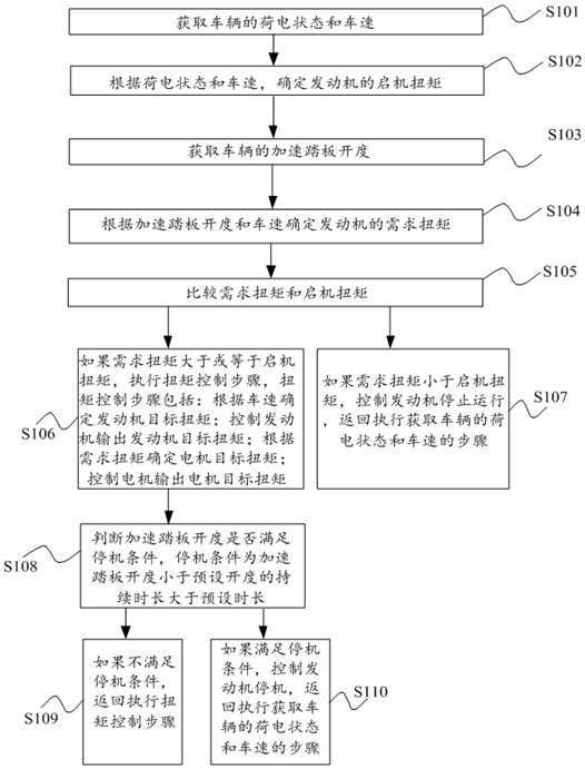
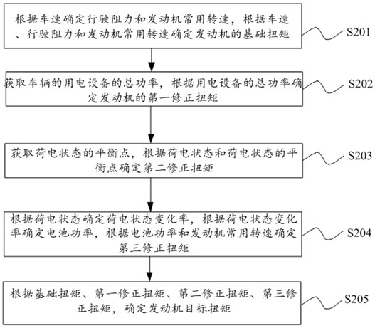
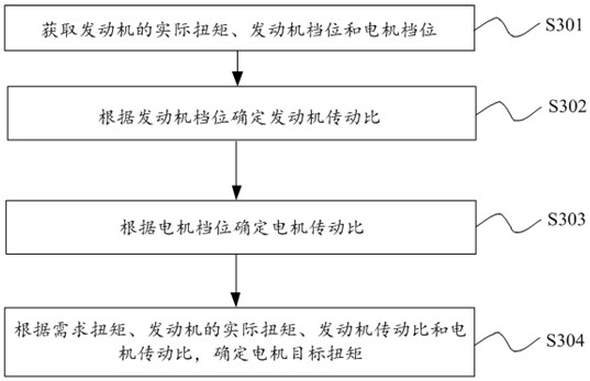
[0060] combine Figure 1 to Figure 3 As shown, the vehicle torque determination method provided in Embodiment 1 includes:

[0061] Step S101: Obtain the state of charge and vehicle speed of the vehicle;

[0062] Step S102: Determine the starting torque of the engine according to the state of charge and the vehicle speed;

[0063] Step S103: Obtain the accelerator pedal opening of the vehicle;

[0064] Step S104: Determine the required torque according to the opening of the accelerator pedal and the vehicle speed;

[0065] Step S105: comparing the required torque and the starting torque;

[0066] Step S106: If the required torque is greater than or equal to the starting torque, execute the torque control step, the torque control step includes: determining the engine target torque according to the vehicle speed; controlling the engine to output the engine target torque; determining the motor target torque according to the demand torque; controlling the motor to output the mot...

Embodiment 2

[0092] combine Figure 4 As shown, this embodiment 2 provides a vehicle torque determination device 100 for performing the above method, the device includes a first acquisition module 10, a starting torque determination module 30, a second acquisition module 20, a demand torque determination module 40 , a comparison module 50, a first control module 60 and a second control module 70; the first acquisition module 10 is used to obtain the state of charge and the speed of the vehicle; the starting torque determination module 30 is used to determine the engine torque according to the state of charge and the speed of the vehicle; The starting torque; the second acquisition module 20 is used to obtain the accelerator pedal opening of the vehicle; the demand torque determination module 40 is used to determine the demand torque according to the accelerator pedal opening and vehicle speed; the comparison module 50 is used to compare the demand torque and the starting torque ; The first...


PUM


Abstract

In order to solve the problem of low engine heat efficiency caused by unstable engine torque in the prior art, the invention provides a vehicle torque determination method and device. The method comprises the steps of acquiring the state of charge and vehicle speed of a vehicle; determining the starting torque of an engine according to the state of charge and the vehicle speed; acquiring the accelerator pedal opening degree of the vehicle ; determining a required torque according to an accelerator pedal opening and the vehicle speed; comparing the required torque with the starting torque; if the required torque is larger than or equal to the starting torque, executing the torque control step and the torque control step comprises the steps of determining the target torque of the engine according to the vehicle speed, and performing correction according to air conditioner accessory power and current SOC; controlling the engine to output engine target torque; determining a motor target torque according to the required torque; controlling the motor to output motor target torque; and if the required torque is smaller than the starting torque, controlling the engine to stop running, andreturning to execute the step of acquiring the charge state and the vehicle speed of the vehicle.

Description

technical field [0001] The present invention relates to the technical field of vehicle control, in particular to a method and device for determining vehicle torque. Background technique [0002] The engine and motor torque distribution method of hybrid electric vehicles is the core technology, which is the key to realize the vehicle's fuel economy and clean environmental protection. [0003] The more common torque distribution strategy is the torque distribution strategy based on certain rules. The main idea of ​​this strategy is to optimize the thermal efficiency of the engine and adjust the charging torque of the motor to shift the operating point of the engine so that the engine can work in the high efficiency range as much as possible. Inside. However, the existing rule-based energy management strategy needs to rely on experience and the energy consumption efficiency of the engine bench to formulate rules, which is difficult to adapt to various actual working conditions...

Claims


Application Information

Patent Timeline
Patent Type & Authority Patents(China)
IPC IPC(8): B60L15/20
CPCB60L15/20B60L2240/10B60L2240/12B60L2240/423B60L2240/443Y02T10/72
Inventor 张剑锋姜博郭思阳杨超群
Owner ZHEJIANG GEELY HOLDING (GROUP) CO LTD
Learn More