Joint detection kit for differential diagnosis of benign ascites and malignant ascites
A technology of differential diagnosis and combined detection, applied in the medical field, can solve the problems of waste of time in taking out reagents, inability to fix reagents of various sizes, and inability to reuse kits, etc. The effect of fixed effects
- Summary
- Abstract
- Description
- Claims
- Application Information
AI Technical Summary
Problems solved by technology
Method used
Image

Examples
Embodiment 1
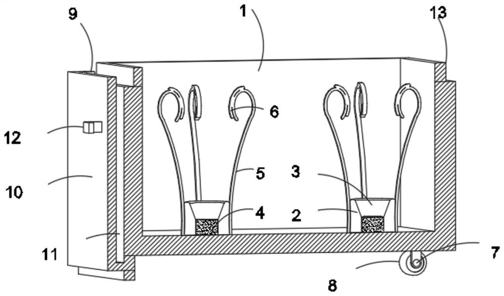
[0032] see Figure 1-3 , a joint detection kit for the differential diagnosis of benign and malignant ascites, comprising a sliding box 1, a fixed lid 14 and a protective box 26, the fixed lid 14 is located on the top of the sliding box 1, and the protective box 26 is sleeved on the outside of the sliding box 1 Surface, also includes:
[0033]The fixing seat 2 arranged on the lower inner wall of the sliding box 1, the sliding box 1 fixes the fixing seat 2, the top of the fixing seat 2 is provided with a trapezoidal groove 3, and the fixing seat 2 can fix the bottom end of the reagent through the trapezoidal groove 3, fix The bottom of the inner wall of the seat 2 is fixedly embedded with a placement pad 4. The placement pad 4 is made of a soft rubber material, which can absorb shock when the reagent is impacted or vibrated, and protect the reagent. The outer surface of the fixed seat 2 is along the circumferential direction. There are four curved spring pieces 5 equidistantly...
Embodiment 2
[0036] see Figure 1-4 , the bottom of the sliding box 1 is fixedly connected with a fixed frame 7 near the right side, the fixed frame 7 can fix the roller 8, and the outer walls of the two sides of the fixed frame 7 are connected with a roller 8, and the roller 8 can reduce the sliding of the sliding box 1. The frictional force between the time and the protection box 26 can facilitate the sliding box 1 to be pulled out or pushed in, and the outer surface of the sliding box 1 and the outer surface of the fixed box cover 14 are all adhered with a sealing strip 9, and the sealing strip 9 can The joint between the sliding box 1 and the protection box 26 is sealed, the sliding box 1 can be further fixed, and the internal reagents can be protected. One side of the outer wall of the sliding box 1 is fixedly connected with a transparent plate 10, and the transparent plate 10 is close to the sliding box 1 One side of the outer wall is provided with a card placement slot 11. The card ...
Embodiment 3
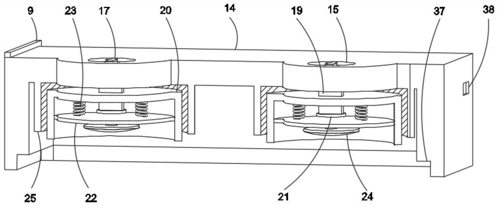
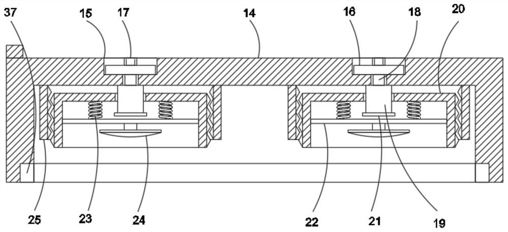
[0038] see Figure 4-7 , the inside of the protection box 26 is set to be hollow, which can facilitate the fixing of the sliding box 1, and the outer walls on both sides of the protection box 26 are provided with sliding openings, and the outer walls on both sides of the protection box 26 are provided with engaging grooves 27, and sealed The bar 9 is embedded in the inside of the engaging groove 27, and the lower inner wall of the protection box 26 is provided with a chute 36, the chute 36 can facilitate the sliding of the box 1 to slide in the protection box 26 through the roller 8, and the inside of the protection box 26 is fixedly embedded. A fixed box 34 is provided, and the fixed box 34 can fix the rotating bayonet rod 33 through the through hole 35. The outer walls of both sides of the fixed box 34 are provided with through holes 35, and the fixed box 34 can pass through the through hole 35 to rotate the bayonet rod. 33 for fixing, the top of the protection box 26 is emb...
PUM
 Abstract
Description
Claims
Application Information