Reverse osmosis filter element and water purifier

A technology of reverse osmosis filter element and reverse osmosis membrane, which is applied in the direction of osmosis/dialysis water/sewage treatment, water/sewage treatment, non-polluted water treatment, etc. It can solve the problem that the first glass of water is not recommended to drink, and achieve the goal of reducing the TDS value Effect

Pending Publication Date: 2020-11-03
FOSHAN MICRO MIDEA FILTER MFG CO LTD
View PDF0 Cites 0 Cited by
  • Summary
  • Abstract
  • Description
  • Claims
  • Application Information

AI Technical Summary

Problems solved by technology

[0003] However, the RO membrane is installed in the filter element or the membrane shell, and the proportion of water inflow and waste water in the filter element system is much larger than that of pure water. After the machine is shut down, the water inlet solenoid valve is closed, and the RO filter element forms a closed space. The wastewater in the membrane belt, the inner wall of the filter element and the wastewater end of the RO membrane will be mixed and diluted with the raw water in the filter element, so that the TDS of the water inlet end in the entire filter element is very high, and this part of the water is more. When the machine is started again, the water inflow When the solenoid valve is opened, under the action of pressure, the water with high TDS value stored in the filter element will be filtered first, because the TDS value of the incoming water increases, and the TDS value of the pure water that is turned on again naturally will be higher, so generally the first glass of water is not Recommended to drink

Method used

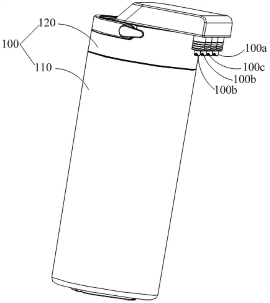
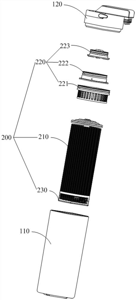
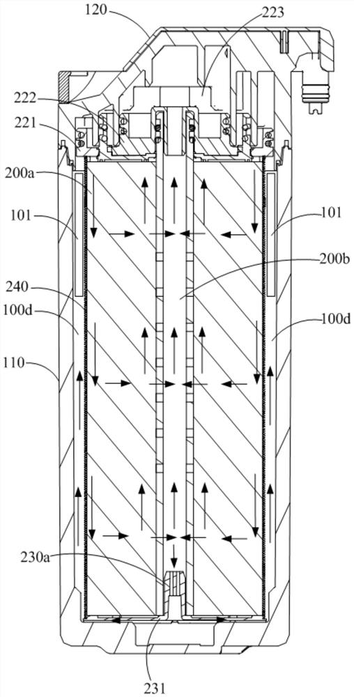

Image

  • Reverse osmosis filter element and water purifier
  • Reverse osmosis filter element and water purifier
  • Reverse osmosis filter element and water purifier

Examples


Embodiment Construction

[0037] The technical solutions in the embodiments of the present invention will be clearly and completely described below in conjunction with the accompanying drawings in the embodiments of the present invention. Obviously, the described embodiments are only a part of the embodiments of the present invention, rather than all the embodiments. Based on the embodiments of the present invention, all other embodiments obtained by those of ordinary skill in the art without creative work shall fall within the protection scope of the present invention.

[0038] It should be noted that all directional indications (such as up, down, left, right, front, back...) in the embodiments of the present invention are only used to explain the relationship between the components in a particular posture (as shown in the accompanying drawings). If the relative position relationship, movement situation, etc. change, the directional indication will change accordingly.

[0039] In addition, descriptions rel...


PUM


Abstract

The invention discloses a reverse osmosis filter element and a water purifier. The reverse osmosis filter element comprises a shell assembly and a reverse osmosis membrane assembly; the shell assemblyis provided with a mounting cavity, and a raw water inlet, a concentrated water outlet and a pure water outlet which are respectively communicated with the mounting cavity; the reverse osmosis membrane assembly is mounted in the mounting cavity and is used for carrying out osmosis filtration treatment on the raw water to generate concentrated water and pure water, the reverse osmosis membrane assembly is provided with a filtering area and a pure water area, the filtering area is respectively communicated with the raw water inlet and the concentrated water outlet, and the pure water area is communicated with the pure water outlet; wherein a pressure maintaining water storage chamber is defined by the peripheral wall of the reverse osmosis membrane assembly and the inner wall of the shell assembly, a pure water channel of the pure water area is communicated with the pressure maintaining water storage chamber, and a pressure maintaining member is arranged in the pressure maintaining water storage chamber. According to the invention, the structure of the reverse osmosis filter element is improved, the backwashing function is realized, and the problem of high TDS value of the first cupof water is solved, so that a user can directly drink the first cup of water.

Description

Technical field [0001] The invention relates to the technical field of reverse osmosis filter elements, in particular to a reverse osmosis filter element and a water purifier. Background technique [0002] The existing reverse osmosis filter element (Reverse Osmosis, RO) has two structures. One is that the RO membrane is equipped with a Y-shaped sealing ring to separate the raw water from the waste water, that is, one end of the RO membrane is the inlet water, the other end is the waste water, and the center tube Pure water is discharged; the other is to seal the upper and lower ends with glue, leaving a circle of holes in the upper end cover to drain the waste water, the water is flushed to the side to enter the water, the lower end cover is sealed, and the center tube is drained of pure water. [0003] However, the RO membrane is installed in the filter element or the membrane shell, and the proportion of influent water and wastewater in the filter element system is much greater ...

Claims


Application Information

Patent Timeline
Patent Type & Authority Applications(China)
IPC IPC(8): C02F1/44C02F103/04
CPCC02F1/441C02F2103/02C02F2201/004C02F2209/10C02F2303/14
Inventor 罗安泺玄珍雨
Owner FOSHAN MICRO MIDEA FILTER MFG CO LTD
Why Eureka
Try Eureka