
A swirl biological fluidized bed reactor and its operating method

A biological fluidized bed and reactor technology, applied in chemical instruments and methods, biological treatment devices, sustainable biological treatment, etc., can solve the problems of low sludge concentration, low biochemical treatment efficiency, and difficulty in improving removal efficiency, etc. The effect of reducing the amount of treatment and increasing the sludge concentration

Active Publication Date: 2022-08-09
NANJING UNIV
View PDF11 Cites 0 Cited by
  • Summary
  • Abstract
  • Description
  • Claims
  • Application Information

AI Technical Summary

Problems solved by technology

[0003] Because the contact frequency of sewage and biofilm is higher than that of conventional bio-filled tanks, the removal rate of pollutants by biological fluidized bed is higher, but there are still some defects in its application process
If the fluidization state of the filler is not good and the sludge concentration is low, it is difficult to improve the removal efficiency. Chinese invention patent CN20150652524.3 discloses a new type of aerobic biological fluidized bed reactor and its process. The reactor includes support, reactor Tanks, external pumps and inclined plate clarifiers, etc.
However, the reactor uses the supernatant as the reflux liquid, which cannot quickly increase the sludge concentration inside the reactor, resulting in low biochemical treatment efficiency, limited sewage treatment scenarios, and is only suitable for specific sewage treatment

Method used


Image

  • A swirl biological fluidized bed reactor and its operating method
  • A swirl biological fluidized bed reactor and its operating method
  • A swirl biological fluidized bed reactor and its operating method

Examples


Embodiment 1

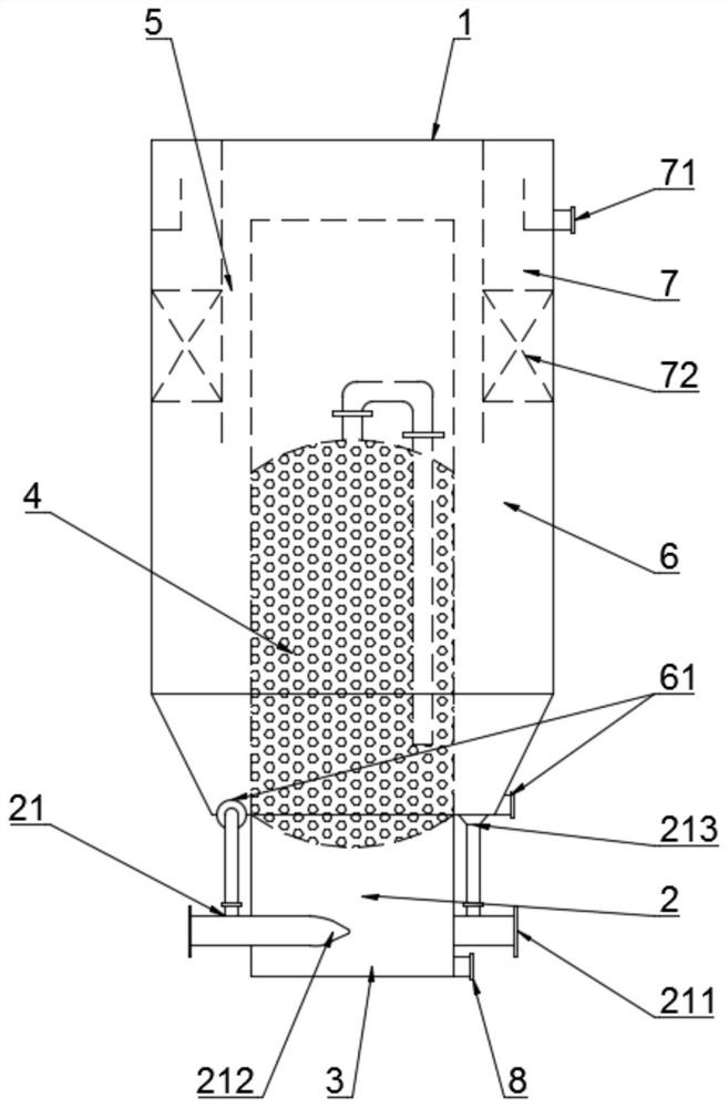
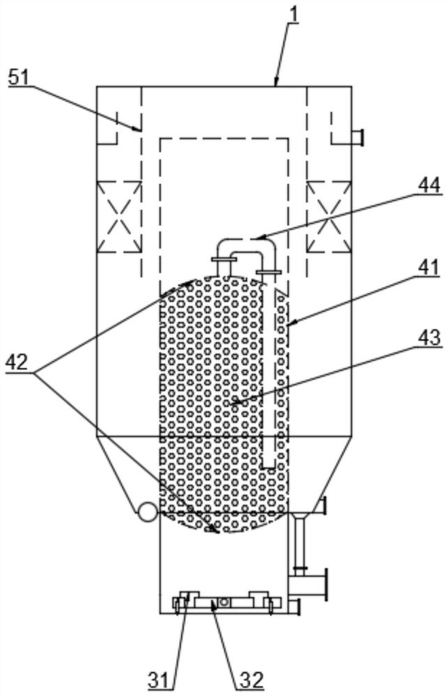
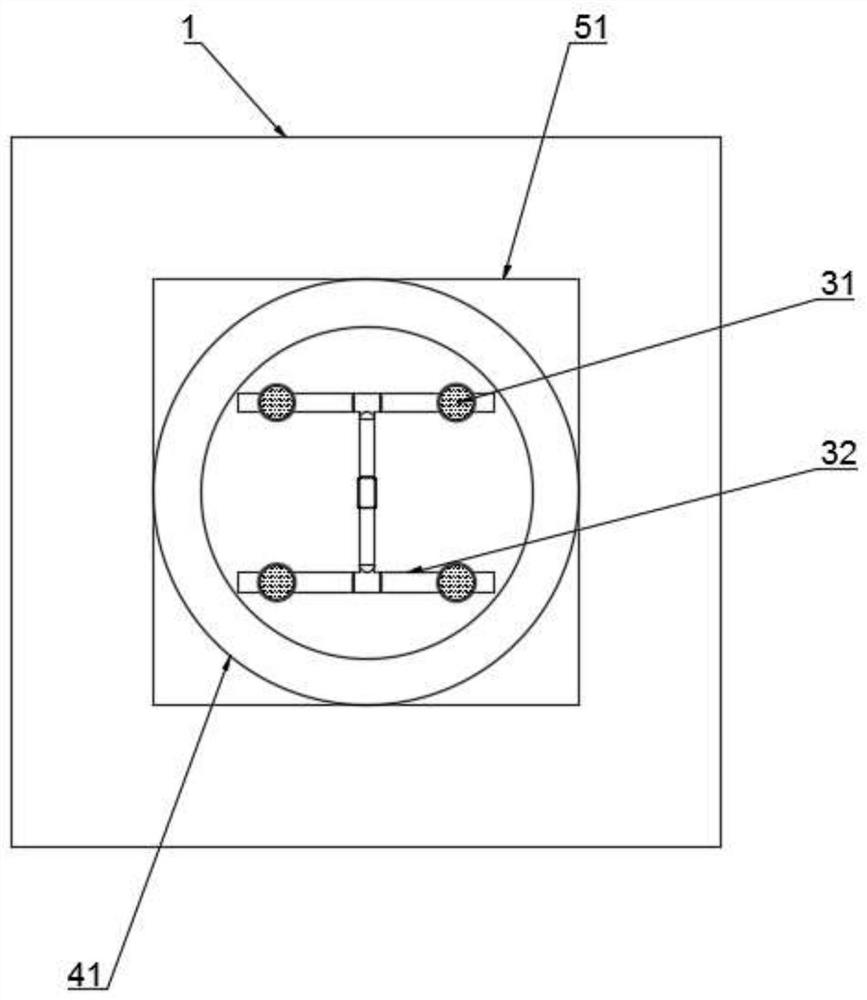
[0038] like Figures 1 to 4 As shown, a swirling biological fluidized bed reactor includes a reactor shell 1 with a water outlet 7 on the upper end sidewall and a second mud discharge port 61 on the lower end sidewall, and the inner cavity of the reactor shell 1 is provided with There is a reactor 41, and the bottom side wall of the reactor 41 is provided with a first mud discharge port 8, and its specific structure is as follows:

[0039] The reactor 41 extends into the inner cavity of the reactor shell 1 and is provided with a packing reaction zone 4. The part of the inner cavity of the reactor 41 that extends out of the reactor shell 1 is divided into a swirl reaction zone 2 and an aeration zone from top to bottom. 3.

[0040] Two ejectors 21 are oppositely arranged along the outer wall of the swirling reaction zone 2 of the reactor 41; the ejector inlet 211 of the ejector 21 is connected to the lift pump, and the ejector suction pipe 213 of the ejector 21 and the correspo...

Embodiment 2

[0049] Except for the following contents, the rest of Embodiment 2 and Experiment 1 are the same:

[0050] The swirling reaction zone 2 of the reactor 41 is provided with three jets 21 at intervals along the outer wall, and the angle between the three jets 21 is 120°; the jet inlet 211 of the jet 21 is connected to the lift pump, and the jet The ejector suction pipe 213 of the reactor 21 is connected to the corresponding second mud discharge port 61 , and the ejector outlet 212 of the ejector 21 enters the reactor 41 tangentially along the side wall of the reactor 41 .

Embodiment 3

[0052] Except for the following contents, the rest of Embodiment 3 and Experiment 1 are the same:

[0053] The swirling reaction zone 2 of the reactor 41 is provided with four jets 21 at intervals along the outer wall, and the included angle between the four jets 21 is 90°; the jet inlet 211 of the jet 21 is connected to the lift pump, The ejector suction pipe 213 of the ejector 21 is connected to the corresponding second mud discharge port 61 , and the ejector outlet 212 of the ejector 21 enters the reactor 41 tangentially along the side wall of the reactor 41 .


PUM

PropertyMeasurementUnit
diameteraaaaaaaaaa
clearance rateaaaaaaaaaa

Abstract

The invention relates to the technical field of sewage biological treatment, in particular to a swirling biological fluidized bed reactor, comprising a swirling reaction zone, an aeration zone, a packing reaction zone, a transition zone, a sedimentation zone and a water outlet zone; a swirling reaction zone It consists of jets and pipelines, the aeration zone is composed of microporous aerators and aeration pipelines, the packing reaction zone includes suspended biological fillers, baffles and reflux collection devices, and the sedimentation zone includes barrier devices and water outlet tanks; using this The invention can quickly increase the sludge concentration in the reactor, optimize the fluidization of sewage and fillers in the reactor, and effectively increase the removal load of pollutants; and the invention is convenient to operate, and has a reasonable integrated design, and is suitable for conventional and Emergency treatment, easy to popularize and apply.

Description

technical field [0001] The invention relates to the technical field of sewage biological treatment, in particular to a jet-swirling biological fluidized bed reactor and an operating method thereof. Background technique [0002] Biological fluidized bed is a sewage treatment process that combines traditional activated sludge process and biofilm process and introduces fluidization technology. It has the characteristics of activated sludge process and biofilm process. The membrane method has the characteristics of high load and good removal effect of organic matter. [0003] Because the contact frequency of sewage and biofilm is higher than that of conventional biological filling tank, the removal rate of pollutants by biological fluidized bed is higher, but there are still some defects in its application process. For example, the fluidization state of the filler is poor and the sludge concentration is low, which makes it difficult to improve the removal efficiency. Chinese in...

Claims


Application Information

Patent Timeline
Patent Type & Authority Patents(China)
IPC IPC(8): C02F3/12
CPCC02F3/1236C02F2203/006Y02W10/10
Inventor 黄辉彭冲范林任洪强
Owner NANJING UNIV
Learn More