Vortex biological fluidized bed reactor and operation method thereof
A biological fluidized bed and reactor technology, applied in chemical instruments and methods, biological treatment devices, sustainable biological treatment, etc., can solve the problems of low biochemical treatment efficiency, low sludge concentration, and limited sewage treatment scenarios. Achieving the effect of avoiding loss and improving precipitation efficiency
- Summary
- Abstract
- Description
- Claims
- Application Information
AI Technical Summary
Problems solved by technology
Method used
Image
Examples
Embodiment 1
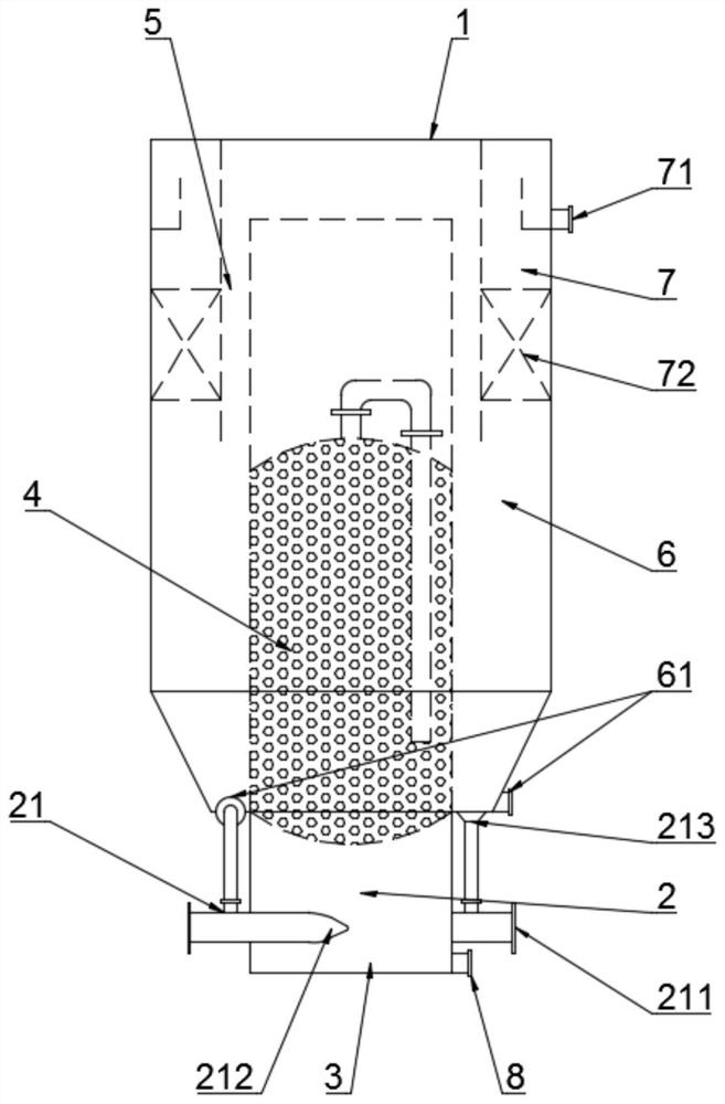
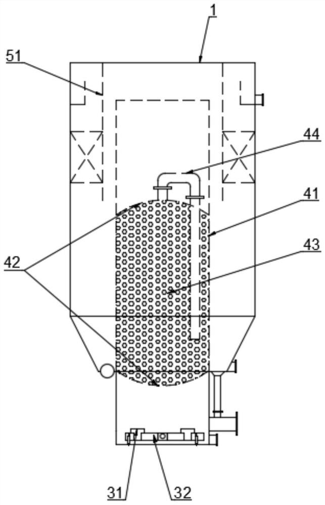
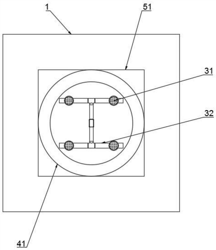
[0038] like Figure 1~4 As shown, a swirling biological fluidized bed reactor includes a reactor shell 1 with a water outlet 7 on the upper end sidewall and a second mud discharge port 61 on the lower end sidewall, and the inner cavity of the reactor shell 1 is provided with There is a reactor 41, and the bottom side wall of the reactor 41 is provided with a first mud discharge port 8, and its specific structure is as follows:
[0039] The reactor 41 extends into the inner cavity of the reactor shell 1 and is provided with a packing reaction zone 4. The part of the inner cavity of the reactor 41 that extends out of the reactor shell 1 is divided into a swirl reaction zone 2 and an aeration zone from top to bottom. 3.
[0040] Two ejectors 21 are oppositely arranged along the outer wall of the swirling reaction zone 2 of the reactor 41; the ejector inlet 211 of the ejector 21 is connected to the lift pump, and the ejector suction pipe 213 of the ejector 21 and the correspondin...
Embodiment 2
[0049] Embodiment two and experimental example one except the following content, all the other parts are the same:
[0050] The vortex reaction zone 2 of the reactor 41 is provided with three ejectors 21 at intervals along the outer wall, and the angle between two of the three ejectors 21 is 120°; the ejector inlet 211 of the ejector 21 is connected with the lift pump, and the jet The ejector suction pipe 213 of the ejector 21 is connected to the corresponding second mud outlet 61 , and the ejector outlet 212 of the ejector 21 enters the interior of the reactor 41 tangentially along the side wall of the reactor 41 .
Embodiment 3
[0052] Embodiment three and experimental example one except the following content, all the other parts are the same:
[0053] The vortex reaction zone 2 of the reactor 41 is provided with four injectors 21 at intervals along the outer wall, and the angle between two of the four injectors 21 is 90°; the injector inlet 211 of the injector 21 is connected to the lift pump, The ejector suction pipe 213 of the ejector 21 is connected to the corresponding second mud outlet 61 , and the ejector outlet 212 of the ejector 21 enters the reactor 41 tangentially along the side wall of the reactor 41 .
PUM
| Property | Measurement | Unit |
|---|---|---|
| diameter | aaaaa | aaaaa |
| clearance rate | aaaaa | aaaaa |
| clearance rate | aaaaa | aaaaa |
Abstract
Description
Claims
Application Information
 - R&D
- Intellectual Property
- Life Sciences
- Materials
- Tech Scout
- Unparalleled Data Quality
- Higher Quality Content
- 60% Fewer Hallucinations
Browse by: Latest US Patents, China's latest patents, Technical Efficacy Thesaurus, Application Domain, Technology Topic, Popular Technical Reports.
© 2025 PatSnap. All rights reserved.Legal|Privacy policy|Modern Slavery Act Transparency Statement|Sitemap|About US| Contact US: help@patsnap.com


