In-situ uranium mine high-power ultrasonic blockage removing and permeability increasing device and method

An ultrasonic, high-power technology, applied in the direction of earthwork drilling, mining fluid, wellbore/well components, etc., can solve the problems of small impact range, high safety risk, lack of formation protection, etc., and achieve recovery ability and low environmental impact Effect

Inactive Publication Date: 2020-11-03
BEIJING RESEARCH INSTITUTE OF CHEMICAL ENGINEERING AND METALLURGY
View PDF9 Cites 7 Cited by
  • Summary
  • Abstract
  • Description
  • Claims
  • Application Information

AI Technical Summary

Problems solved by technology

[0005] The purpose of the present invention is to provide a high-power ultrasonic plugging removal method for in-situ leaching uranium mines to solve the shortcomings of the above various plugg

Method used


Image

  • In-situ uranium mine high-power ultrasonic blockage removing and permeability increasing device and method
  • In-situ uranium mine high-power ultrasonic blockage removing and permeability increasing device and method
  • In-situ uranium mine high-power ultrasonic blockage removing and permeability increasing device and method

Examples


Embodiment 1

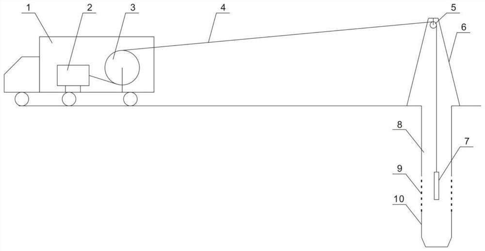
[0037] Such as figure 1 As shown, the present embodiment provides a high-power ultrasonic deblocking and permeation-increasing device for in-situ leaching uranium mines, including an ultrasonic well cleaning vehicle 1, an ultrasonic special cable 4, a wellhead bracket 6, a pulley 5 and an ultrasonic transducer 7; The support 6 is arranged at the wellhead of the injection fluid well, the pulley 5 is arranged on the wellhead support 6, one end of the ultrasonic special cable 4 is arranged on the ultrasonic well cleaning vehicle 1, and the other end bypasses the pulley 5 and then extend into the injection fluid well, and the ultrasonic transducer 7 is arranged at the end of the other end of the ultrasonic special cable 4 .

[0038] The ultrasonic well cleaning vehicle 1 includes a carrier vehicle, an ultrasonic transmitter 2 and a winch 3; the ultrasonic transmitter 2 and the winch 3 are all arranged in the carrier vehicle, and the ultrasonic special cable 4 is arranged in the wi...

Embodiment 2

[0042] This embodiment discloses a method based on the high-power ultrasonic plugging-removing and permeation-increasing device for in-situ leaching uranium mines in Embodiment 1, including the following steps:

[0043](1) Pull out the liquid injection pipeline in the liquid injection well or the liquid suction submersible pump in the liquid suction well;

[0044] (2) align the wellhead bracket 6 with the wellhead of the pumping liquid well, and install the pulley 5 on the derrick;

[0045] (3) Align the ultrasonic well cleaning vehicle 1 with the wellhead support 6, so that the ultrasonic well cleaning vehicle 1, the wellhead support 6, and the wellhead of the pumping and injection well are located on a straight line;

[0046] (4) Lower the ultrasonic transducer 7 into the injection well, the ultrasonic transducer 7 is connected with the ultrasonic special cable 4, the ultrasonic special cable 4 is connected with the ultrasonic transmitter 2, and the ultrasonic special cable ...


PUM

PropertyMeasurementUnit
Average power densityaaaaaaaaaa

Abstract

The invention discloses an in-situ leaching uranium mine high-power ultrasonic blockage removing and permeability increasing device and method, and relates to the technical field of in-situ leaching uranium mining. The main structure of the device comprises an ultrasonic well washing vehicle, an ultrasonic special cable, a wellhead support, a pulley and an ultrasonic transducer, wherein the wellhead support is arranged at the wellhead of a liquid pumping and injecting well, the pulley is arranged on the wellhead support, one end of the ultrasonic special cable is arranged on the ultrasonic well washing vehicle, and the other end of the ultrasonic special cable bypasses the pulley and then extends into the liquid pumping and injecting well; and the ultrasonic transducer is arranged at the end part of the other end of the special ultrasonic cable. Scales on a filter are oscillated and removed through the ultrasonic transducer, and then compressed air is injected through the air compressor to discharge the scales and water at the same time, so that the scales on the filter and near wellbore zones are safely and effectively removed, the well drilling liquid pumping and injecting capacity is effectively recovered, and influence on the environment is small.

Description

technical field [0001] The invention relates to the technical field of in-situ leaching uranium mining, in particular to an in-situ leaching uranium mine high-power ultrasonic plugging-removing and permeability-increasing device and method. Background technique [0002] In-situ leaching uranium mining technology is a kind of special solution that only needs to be injected into the underground ore-bearing aquifer through drilling on the surface. The solution selectively dissolves uranium in the ore during the process of underground seepage, and the formed leachate is lifted to the surface. A mining and smelting process for extracting and recovering uranium metal. This technology requires a certain length of filter to be installed in the ore-bearing section of the well to ensure the smooth passage of the solution. However, during the production and operation of in-situ leaching uranium mines, scales are often formed on the filter and the surrounding area near the wellbore, ca...

Claims


Application Information

Patent Timeline
IPC IPC(8): E21B43/16E21B21/00E21B21/16
CPCE21B43/16E21B21/00E21B21/16
Inventor 杜志明李宏星廖文胜刘双民
Owner BEIJING RESEARCH INSTITUTE OF CHEMICAL ENGINEERING AND METALLURGY
Why Eureka
Try Eureka