
A coal mine dust removal system and dust removal method

A dust removal system and coal mine technology, which is applied in mine safety comprehensive management projects, mine excavation, drilling, fully mechanized mining dust removal and tunnel construction, can solve the problems of failure to meet safety regulations, low dust removal efficiency, and large water consumption. Achieve the effect of saving transportation equipment, long operation cycle and reducing water consumption

Active Publication Date: 2022-06-07
DALIAN EAST REFRIGERATION EQUIP
View PDF6 Cites 0 Cited by
  • Summary
  • Abstract
  • Description
  • Claims
  • Application Information

AI Technical Summary

Problems solved by technology

The device meets the requirements of wet dust removal by spraying water, but the water consumption is large, and the effect of dust removal is limited by the baffle effect.
And Chinese patent CN103925000A discloses a kind of negative pressure dedusting device for coal mines. A filtering device is set between the air inlet and the air outlet. Low, low dust removal rate
[0004] Most of the existing coal mining face dust removal and drilling dust removal adopts high-pressure water spray dust suppression or high-pressure water ejection dust removal, which has the problems of large water consumption and low dust removal efficiency, and cannot meet the standards required by safety regulations

Method used


Image

  • A coal mine dust removal system and dust removal method
  • A coal mine dust removal system and dust removal method
  • A coal mine dust removal system and dust removal method

Examples


Embodiment 1

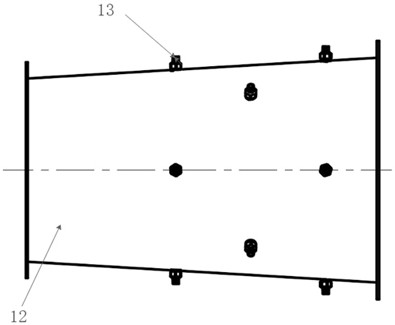
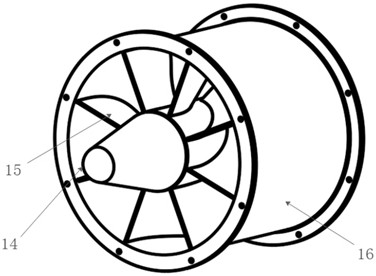
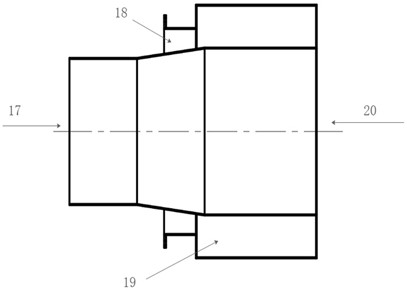
[0041] like Figure 1 to Figure 8 As shown, the coal mine dust removal system according to the present embodiment 1 includes a collection device, a pneumatic suction device 2, a mist dust removal device 3, a cyclone separation device 4, a multiphase flow separation device 5 and a dust collector 6 connected in sequence, The trapping device, the pneumatic suction device 2, the mist dust removal device 3, the cyclone separation device 4 and the multiphase flow splitting device 5 are all tubular structures, and there is a gap between two adjacent devices. It is an integrated structure through flange connection, the pneumatic suction device 2 is softly connected to the coal mine ventilation pipe through a retractable hose, and the slag discharge port of the multi-phase flow dividing device 5 is softly connected to the coal mine slag discharge system through a retractable pipe. , the mist dust removal device 3 is connected to the coal mine water supply system through a hose, and a s...

Embodiment 2

[0057] The coal mine dust removal method according to the present embodiment 2 comprises the following steps:

[0058] Step (1) Move the construction equipment carrying the coal mine dust removal system to the work area, and place the capture device in the designated dust removal area through a telescopic pipe;

[0059] Step (2) Open the valve of the nozzle 13 of the mist dust removal device 3 and the shut-off valve of the coal mine water supply system;

[0060] Step (3) gradually open the coal mine ventilation pipe of the coal mine ventilation system and the stop valve of the ejector 1 in the pneumatic suction device 2, start the ejector 1, and the dust-laden gas enters the pneumatic suction device 2 through the suction chamber;

[0061] Step (4) The water curtain formed by the nozzle 13 of the mist dedusting device 3 adsorbs, wets and condenses the dust in the dust-laden gas, depressurizes the outlet end of the mist dedusting device 3, and accelerates into the cyclone separa...

Embodiment 3

[0069] The coal mine dust removal system of the present embodiment 3 is applied to the dust removal of a certain coal mine working face, and the conditions of the working face are as follows:

[0070]

[0071] By calculating the air volume of the working face, a coal mine dust removal system composed of four pneumatic suction devices 2 is selected to deal with the working face dust.

[0072]When in use, place the collector on the designated dust removal work surface through the telescopic pipe, and connect the coal mine dust removal system with the coal mine air supply and water supply system pipes; after opening the nozzle 13 of the mist dust removal device 3 and the coal mine supply water valve, gradually open The shut-off valve of the ejector 1 of the coal mine ventilation system and the pneumatic suction device 2, the high-pressure air for coal mine ventilation is introduced into the pneumatic suction device 2 from the high-pressure tuyere 9, and the ejector 1 is activat...


PUM


Abstract

The invention discloses a coal mine dedusting system and a dedusting method, comprising sequentially connected capture devices, pneumatic suction devices, mist dedusting devices, cyclone separation devices, multi-phase flow diversion devices and dust collectors, the capture device , the pneumatic suction device, the mist dust removal device, the cyclone separation device and the multi-phase flow diversion device are all tubular structures and two adjacent devices are connected as a whole by flanges, the pneumatic The suction device is connected to the coal mine ventilation pipe through a telescopic hose, the slag outlet of the multi-phase diversion device is connected to the coal mine slag discharge system through a telescopic pipe, and the mist dust removal device is connected to the coal mine water supply system through a hose. A cut-off valve is arranged on the flexible hose and the pipeline of the hose. The unit combination design of the coal mine dust removal system of the present invention is reasonable in design, small in size, has the advantages of less investment, small footprint, low energy consumption, and high dust removal rate. The coal mine dust removal method of the present invention has the advantages of short process and low operating costs.

Description

technical field [0001] The invention relates to the technical field of mine safety comprehensive treatment engineering, relates to a coal mine underground dustproof and dust reduction project, in particular to the fields of mine excavation, drilling, fully mechanized mining dust removal and tunnel construction, in particular to a coal mine dust removal system and Dust removal method. Background technique [0002] The existing coal mine dust removal methods are mainly divided into two categories: one is dry dust removal device, which is composed of bag filter, settling chamber, dust catcher and dust removal fan. Pressure suction dust-laden airflow. The advantage is that the dust removal rate is high, but the disadvantage is that the cloth bag is easy to block, the service life is not long, and the equipment is bulky, the installation and construction are cumbersome, and it is not easy to move; the other type is the wet dust removal device, which consists of a wet dust remova...

Claims


Application Information

Patent Timeline
Patent Type & Authority Patents(China)
IPC IPC(8): E21F5/04E21F5/20E21C35/22B01D50/40
CPCE21F5/04E21F5/20E21C35/22E21C35/223B01D50/40Y02A50/2351
Inventor 袁君王金海蔡振义周立杰
Owner DALIAN EAST REFRIGERATION EQUIP
Learn More