Wind power generation device for high-temperature flue gas mechanical cooler, and power generation method

A technology of wind power generation device and high temperature flue gas, which is applied to wind turbines, wind power generation, wind turbines and other directions at right angles to the wind direction to achieve the effect of zero energy consumption

Inactive Publication Date: 2020-11-03
GUIZHOU HUANKE ENVIRONMENT ECOLOGICAL RES & DEV CO LTD
View PDF8 Cites 8 Cited by
  • Summary
  • Abstract
  • Description
  • Claims
  • Application Information

AI Technical Summary

Problems solved by technology

[0003] The present invention intends to provide a wind power generation device using a high-temperature flue gas mechanical co

Method used


Image

  • Wind power generation device for high-temperature flue gas mechanical cooler, and power generation method
  • Wind power generation device for high-temperature flue gas mechanical cooler, and power generation method
  • Wind power generation device for high-temperature flue gas mechanical cooler, and power generation method

Examples


Embodiment 1

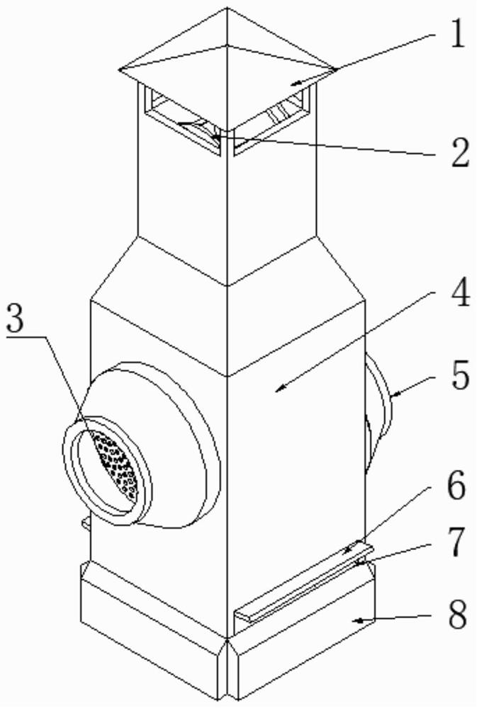
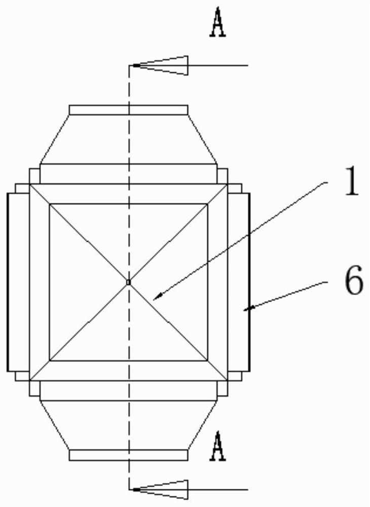
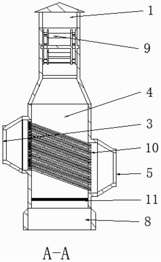
[0019] Embodiment 1 is basically as attached Figure 1~3 Shown: a wind power generation device of a high-temperature flue gas mechanical cooler, including a base 8, a box 4 and a heat exchanger, the bottom of the box 4 is connected to the base 8, and the top of the box 4 is connected to the chimney 1 , a vertical axis wind generator 2 is provided on the box body 4 near the chimney 1, a cold air inlet 7 is provided on the box body 4 near the base 8, and a heat exchanger 10 is arranged on the box body 4, and is located in the cold wind Above the inlet 7, the heat exchanger includes a high-temperature flue gas inlet 5, a heat exchange tube 10, and a high-temperature flue gas outlet 3. The high-temperature flue gas inlet 5 and the high-temperature flue gas outlet 3 are respectively located on opposite sides of the box body 4. 10 is arranged obliquely downward, and the two ends of the heat exchange tube 10 are connected to the high-temperature flue gas inlet 5 and the high-temperat...

Embodiment 2

[0022] The difference between Embodiment 2 and Embodiment 1 is that a plurality of vertical axis wind generators 2 are provided, and the plurality of vertical axis wind generators 2 are installed sequentially from top to bottom, and only one generator is provided.

Embodiment 3

[0023] The difference between embodiment 3 and embodiment 1 is that the heat exchange tube 10 is arranged obliquely downward, and the inclination angle is 30°.

[0024] Through the wind power generation device of the above-mentioned high-temperature flue gas mechanical cooler, wind power generation can be carried out. The chimney 1 is rectangular or square. The height of the chimney 1 is at least 20 meters. The high-temperature flue gas inlet 5 enters the heat exchange tube 10, and the cold air enters from the cold air inlet 7 under the action of the chimney 1, flows through the surface of the heat exchange tube 10 and contacts the heat exchange tube 10 to cool the high-temperature flue gas, The cooled high-temperature flue gas is discharged from the high-temperature flue gas outlet 3, and the temperature of the heated cold air rises to become hot air, which flows upwards and reaches the vertical axis wind turbine 2 so that the vertical axis wind turbine 2 The combined wind wh...


PUM


Abstract

The invention discloses a wind power generation device for a high-temperature flue gas mechanical cooler, and belongs to the technical field of wind power generation. The wind power generation devicecomprises a base, a box, a heat exchanger, a chimney and a vertical-axis wind turbine; the bottom of the box is connected to the base, and the top of the box is connected with the chimney; The position, close to the chimney, of the box is provided with the vertical-axis wind turbine, and the position, close to the base, of the box is provided with a cold air inlet; and the position, on the upper part of the cold air inlet, on the box is provided with the heat exchanger, and the heat exchanger comprises a high-temperature flue gas inlet, a heat-exchanging tube and a high-temperature flue gas outlet; and the high-temperature flue gas inlet and the high-temperature flue gas outlet are located in the two opposite sides of the box correspondingly. Energy does not need to be externally providedfor cooling high-temperature flue gas, but cooled upward-flowing hot air can be used for generating electricity of the vertical-axis wind turbine, power generation can be conducted while zero energy is achieved, and thus the wind power generation device is worthy of application and popularization.

Description

technical field [0001] The invention belongs to the technical field of wind power generation, and in particular relates to a wind power generation device of a high-temperature flue gas mechanical cooler and a power generation method thereof. Background technique [0002] The high-temperature dust-laden flue gas produced in large quantities during the operation of industrial furnaces is the main source of air pollution. According to the provisions of the national environmental protection regulations, high-efficiency dust removal equipment must be used to remove the dust in the flue gas to achieve marked emission. At present, bag-type dust collectors with high dust removal efficiency are mostly used at home and abroad. The cooling equipment mostly adopts indirect natural air cooler and indirect mechanical cooler. The indirect natural air cooler uses cold air convection to dissipate heat, so it has the characteristics of low heat exchange efficiency, large heat dissipation ar...

Claims


Application Information

Patent Timeline
IPC IPC(8): F03D9/25F03D9/37F03D3/06F03D80/70
CPCF03D3/06F03D9/25F03D9/37F03D80/70Y02E10/728Y02E10/74
Inventor 张朝友许善文袁志勇赵明伦
Owner GUIZHOU HUANKE ENVIRONMENT ECOLOGICAL RES & DEV CO LTD
Why Eureka
Try Eureka