
Cooker valve body

A valve body and cooker technology, which is applied to valve lifts, valve devices, valve details, etc., can solve problems such as cumbersome setting methods and poor user experience, and achieve the effect of improving experience and ensuring reliability

Active Publication Date: 2021-11-05
NINGBO FOTILE KITCHEN WARE CO LTD
View PDF0 Cites 0 Cited by
  • Summary
  • Abstract
  • Description
  • Claims
  • Application Information

AI Technical Summary

Problems solved by technology

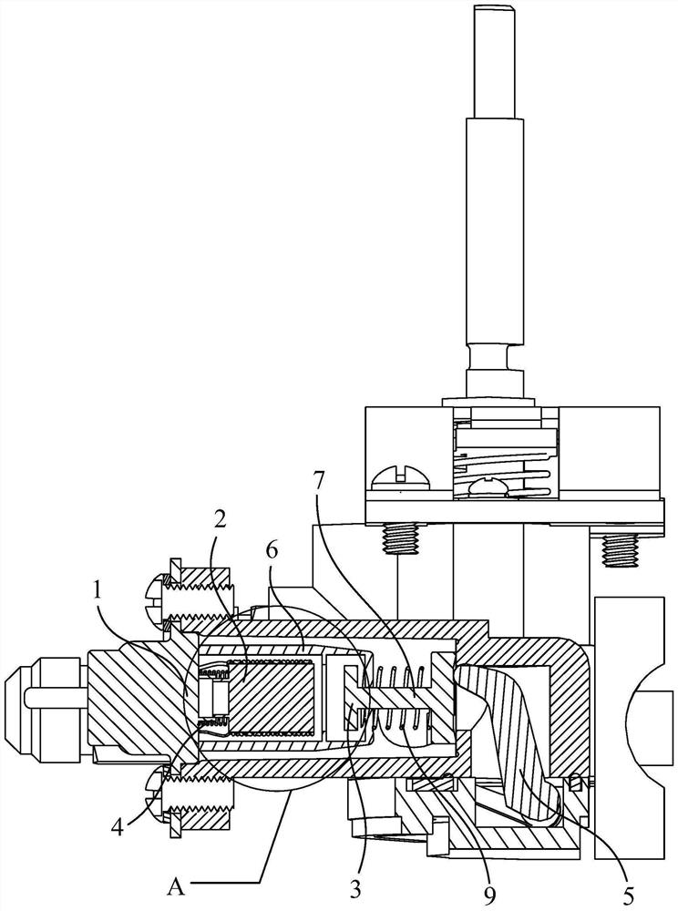
[0004] The technical problem to be solved by the present invention is to provide a cooker valve body in order to overcome the disadvantages of the prior art, such as the relatively cumbersome setting method for absorbing redundant strokes in the solenoid valve and poor user experience.

Method used


Image

  • Cooker valve body
  • Cooker valve body
  • Cooker valve body

Examples


Embodiment 1

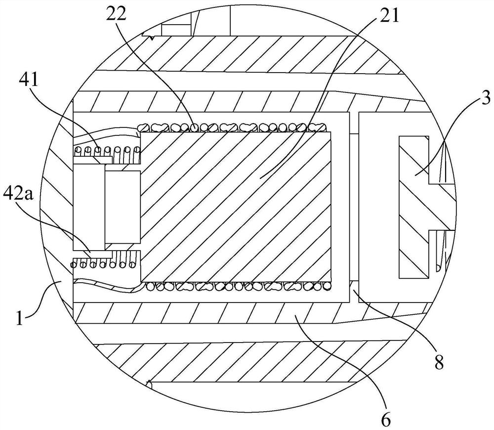
[0044] Such as Figure 1-3 As shown, this embodiment provides a cooker valve body, which includes a solenoid valve, a valve plate 3, a lever 5, a return spring 9 and a valve stem 10, and the user presses the valve stem 10 of the cooker valve body to drive the lever 5 Move and push the valve plate 3 towards the solenoid valve. The solenoid valve includes a valve body 1 and a coil portion 2 , and the coil portion 2 is used to absorb the valve plate 3 . And under the situation that the coil portion 2 does not adsorb the valve plate 3, since the return spring 9 continues to apply a reset force to the valve plate 3 along the suction direction of the valve plate 3 through self compression, the valve plate 3 can be moved under the pressure of the return spring 9. Return to the original position under action.

[0045] In this embodiment, the solenoid valve further includes an elastic assembly 4 through which the coil part 2 is connected to the valve body 1 , and the elastic assembly ...

Embodiment 2

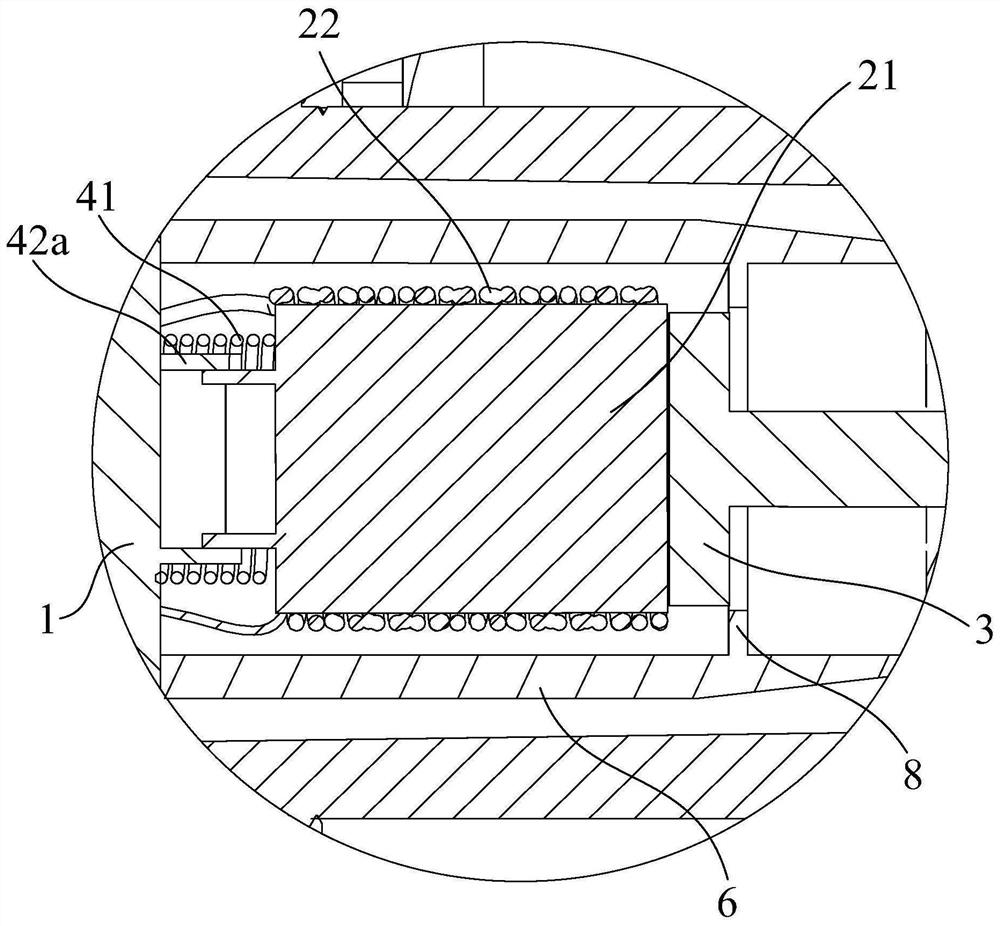
[0054] Such as Figure 4-5 As shown, the basic structure of this embodiment is basically the same as that of Embodiment 1, the difference lies in the specific structural arrangement of the elastic component 4 .

[0055] In this embodiment, the positioning member 42 is set to be fixed on the sleeve 42b of the valve body 1, the inner spring 41 of the elastic component 4 and one end of the iron core 21 are located in the sleeve 42b, and the sleeve 42b is sleeved on the iron core 21 The outer surface of the sleeve 42b, and the iron core 21 can move relative to the sleeve 42b along the axial direction of the sleeve 42b, and the axial extension direction of the sleeve 42b is the same as the suction direction. The sleeve 42b can play a certain protective role, and also make the positioning effect of the valve body 1 and the iron core 21 better.

[0056] In addition, the surface of the valve body 1 also has a positioning structure 11 extending toward the surface close to the iron cor...


PUM


Abstract

The invention discloses a cooker valve body, which includes a solenoid valve and a valve piece. The solenoid valve includes a valve body part and a coil part. The coil part is used to absorb the valve piece. Connected to the valve body, the elastic component can be compressed along the suction direction of the valve plate. The cooker valve body provided by the present invention is provided with an elastic component inside the electromagnetic valve, which can handle a part of the redundant downward pressure stroke after the electromagnetic valve and the valve plate are attracted, and solves the problem that the existing absorbing stroke uses an external spring. It is more complicated, which ensures the reliability of the electromagnetic valve's pull-in, and also makes the stiffness coefficient of the elastic component no longer need to be larger than the return spring, and also enables the elastic component to be compressed after the valve plate is in place, and the elastic component is compressed to produce The reaction force can be made very small, and the reaction force received by the user after continuing to press the valve plate can also be very small, thereby effectively improving the user experience.

Description

technical field [0001] The invention relates to a cooker valve body. Background technique [0002] Conventional gas cookers all include a cooker valve body structure for opening the gas channel before use. The valve body structure includes a housing, a solenoid valve and a lever located in the housing. The inner wall of the housing forms a gas channel leading to the inside of the cooker. The valve plate of the valve opens or closes the gas channel based on the displacement generated by the user pressing the valve stem. The valve plate cover is set at the opening of the gas channel, and the lever is pressed down by the valve stem to generate a turning motion, which can further drive it against the valve plate. One end of the valve plate is pushed open. In order to ensure that the solenoid valve is fully closed, the distance of the downward pressure is generally longer than the distance from the valve plate to the solenoid valve closed, so it is necessary to absorb the excess...

Claims


Application Information

Patent Timeline
Patent Type & Authority Patents(China)
IPC IPC(8): F16K31/10F16K31/46F16K1/00F16K1/32F16K27/02F24C3/12
CPCF16K1/00F16K1/32F16K27/029F16K31/0655F16K31/0675F16K31/0696F16K31/10F16K31/46F24C3/126
Inventor 苏慧玲俞瑜严力峰
Owner NINGBO FOTILE KITCHEN WARE CO LTD
Learn More