
Multi-dehumidification device for textile fabric

A textile fabric, multi-layer technology, applied in the direction of thin material processing, transportation and packaging, drying solid materials, etc., can solve the problems of time consumption, low drying efficiency, heat waste of drying equipment, etc., and achieve the effect of increasing efficiency and speed

Inactive Publication Date: 2020-11-03
尧国荣
View PDF0 Cites 4 Cited by
  • Summary
  • Abstract
  • Description
  • Claims
  • Application Information

AI Technical Summary

Problems solved by technology

[0002] The original meaning of textile is taken from the general term of spinning and weaving. Modern textile refers to a multi-scale structure processing technology of fibers or fiber aggregates. Dehumidification of textile fabrics is an indispensable step in textile production. In traditional methods, fabrics are It is natural drying, which is too time-consuming and requires a lot of manpower, and is greatly affected by the weather. Now there are special textile dehumidification devices, which are dried by hot air transmission, but the existing hot air drying and dehumidification devices directly The drying box is directly connected to the drying equipment, and air circulation is formed between the atmosphere and the drying box. The hot air in the drying box is directly discharged into the atmosphere, and the drying efficiency is low. Most of the heat generated by the drying equipment is absorbed It is wasteful and has not been effectively utilized; and the speed of dehumidification of textile fabrics only by hot air is relatively slow. For mass production factories, the speed of hot air drying and dehumidification needs to be improved

Method used


Image

  • Multi-dehumidification device for textile fabric
  • Multi-dehumidification device for textile fabric
  • Multi-dehumidification device for textile fabric

Examples


Embodiment Construction

[0020] The following embodiments will describe the present invention in detail with reference to the drawings. In the drawings or descriptions, similar or identical parts use the same symbols, and in practical applications, the shape, thickness or height of each component can be enlarged or reduced. The various embodiments listed in the present invention are only used to illustrate the present invention, and are not intended to limit the scope of the present invention. Any obvious modifications or changes made to the present invention do not depart from the spirit and scope of the present invention.

[0021] The technical solution of this patent will be further described in detail below in conjunction with specific embodiments.

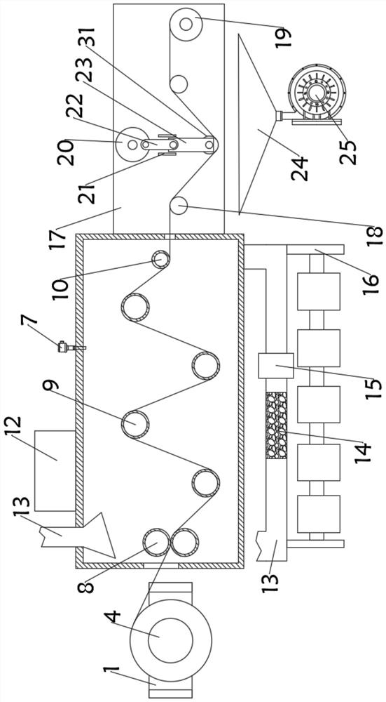
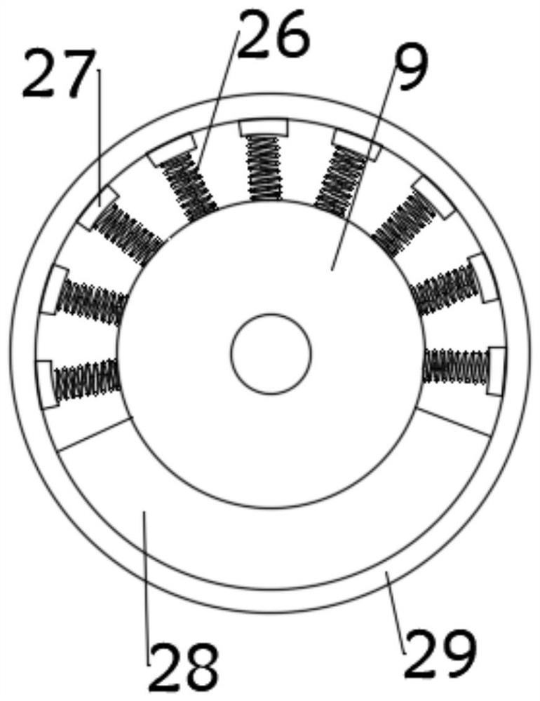
[0022] see figure 1 and figure 2 , this embodiment provides a multiple dehumidification device for textile fabrics, including a primary dehumidification mechanism, a drying dehumidification mechanism, a tensioning dehumidification mechanism, a cool...


PUM


Abstract

The invention discloses a multi-dehumidification device for textile fabric. The device comprises a primary dehumidification mechanism, a drying dehumidification mechanism, a tensioning dehumidification mechanism, a cooling dehumidification mechanism and a winding mechanism, the drying dehumidification mechanism comprises a drying box, and a heating piece communicated with the drying box is arranged above the drying box; and an exhaust pipe communicated with the upper end face and the lower end face of the drying box is arranged outside the drying box, and an exhaust fan used for dehumidifyingand a drying piece used for drying air are arranged on the exhaust pipe. The textile fabric is subjected to multiple dehumidification of the primary dehumidification mechanism, the drying dehumidification mechanism, the tensioning dehumidification mechanism and the cooling dehumidification mechanism in sequence, and the dehumidification efficiency and speed are improved. The exhaust fan and the drying piece in the drying dehumidifying mechanism treat hot air in the drying box and then return the hot air into the drying box, the hot air is recycled, and the utilization rate of heat released bythe heating piece is increased.

Description

technical field [0001] The invention relates to a textile-related device, in particular to a multiple dehumidification device for textile fabrics. Background technique [0002] The original meaning of textile is taken from the general term of spinning and weaving. Modern textile refers to a multi-scale structure processing technology of fibers or fiber aggregates. Dehumidification of textile fabrics is an indispensable step in textile production. In traditional methods, fabrics are It is natural drying, which is too time-consuming and requires a lot of manpower, and is greatly affected by the weather. Now there are special textile dehumidification devices, which are dried by hot air transmission, but the existing hot air drying and dehumidification devices directly The drying box is directly connected to the drying equipment, and air circulation is formed between the atmosphere and the drying box. The hot air in the drying box is directly discharged into the atmosphere, and ...

Claims


Application Information

Patent Timeline
IPC IPC(8): F26B13/08F26B13/14F26B21/00F26B25/20B65H18/10B65H23/26
CPCB65H18/10B65H23/26F26B13/08F26B13/14F26B21/001F26B25/20
Inventor 尧国荣
Owner 尧国荣
Learn More