Automobile environment simulation test cabin

A technology of environmental simulation and test chamber, which is applied in the direction of measuring devices, instruments, scientific instruments, etc., can solve problems such as poor simulation effect and achieve the effect of improving accuracy

Pending Publication Date: 2020-11-03
DONGGUAN CITY SIMPLEWELL TECH
View PDF1 Cites 5 Cited by
  • Summary
  • Abstract
  • Description
  • Claims
  • Application Information

AI Technical Summary

Problems solved by technology

[0004] Aiming at the deficiencies of the prior art, the present invention provides an automobile environment simulation test cabin, which solves the problem in the prior art that the simulation effect is not good when performing simulated light tests on automobiles

Method used


Image

  • Automobile environment simulation test cabin
  • Automobile environment simulation test cabin
  • Automobile environment simulation test cabin

Examples


Embodiment 1

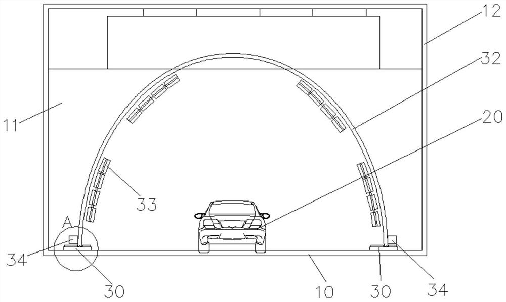
[0046] Please refer to figure 1 with figure 2 , in this embodiment, the bottom platform 10 is provided with a circular track 31, and the circular track 31 is provided with a sunlight simulation system.

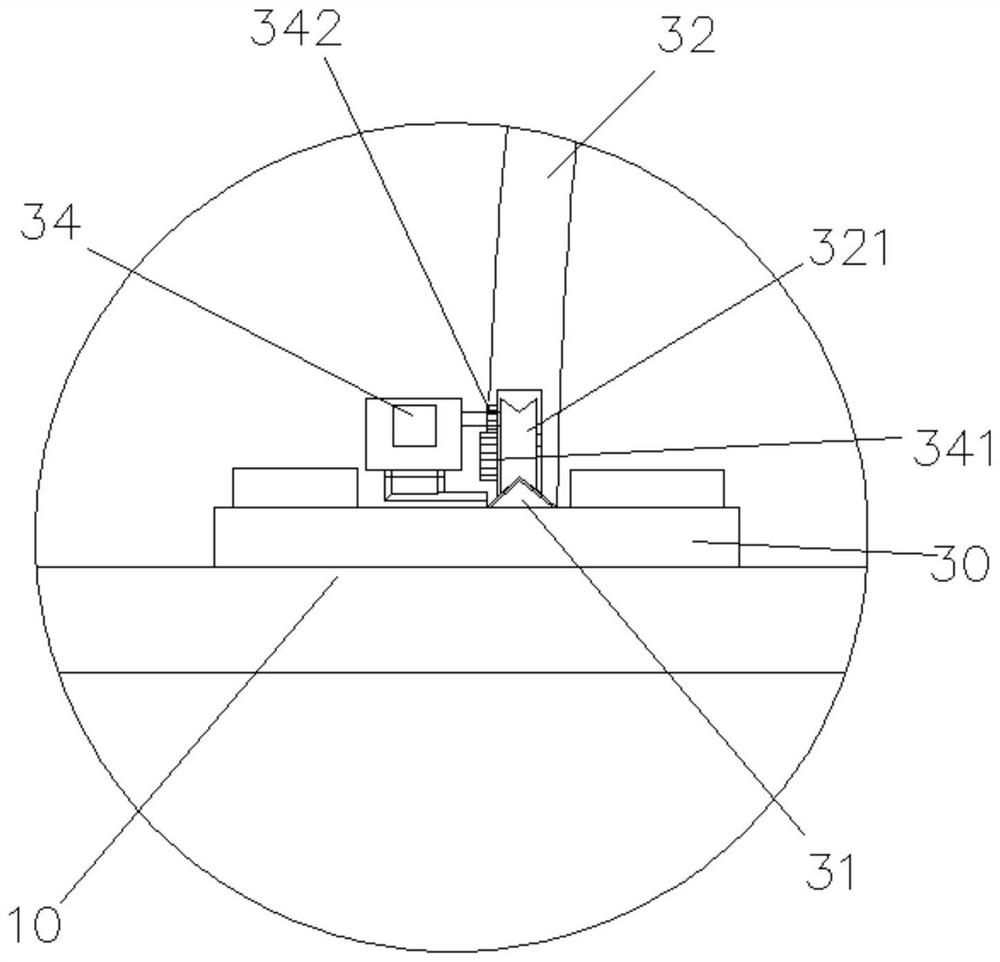
[0047] Wherein, the sunlight simulation system includes an arc-shaped guide rail 32 slidably arranged on the circular track 31 , a driving device for driving and connecting the arc-shaped guide rail 32 , and an irradiation lamp assembly 33 arranged on the arc-shaped guide rail 32 .

[0048] The arc-shaped guide rail 32 is slidably disposed on the circular track 31 and surrounds the outside of the vehicle 20 to be tested. The driving device drives the arc-shaped guide rail 32 to rotate along the circular track 31 . Wherein, a track platform 30 is arranged on the bottom platform 10 , and a circular track 31 is arranged on the track platform 30 .

[0049] Further, the irradiation lamp assembly 33 is slidably arranged on the arc guide rail 32, and the irradiation lamp assembly 33...

Embodiment 2

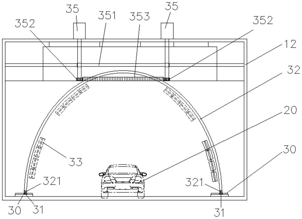
[0058] Based on the above-mentioned embodiments, in this embodiment, the test outer cabin 12 is provided with a flow guide layer, so that an air flow channel 40 is formed between the test outer cabin 12 and the test inner cabin 11 .

[0059] Please refer to Figure 5 , Image 6 , wherein, the airflow channel 40 is provided with a circulating air system for making the air in the test inner cabin 11 form forced convection, and the circulating air system includes a first evaporator 61, a heater and a circulating fan; wherein, the airflow channel 40 is provided with It communicates with the air outlet and air return port of the test inner cabin 11, and is also provided with a fresh air duct 51 for inputting air from the outside, and the fresh air duct 51 communicates with the outside of the test cabin. In addition, an exhaust fan 53 can also be provided in the test inner cabin 11, and the exhaust fan 53 is connected with an exhaust pipe 531. One end of the exhaust pipe 531 is con...


PUM


Abstract

The invention discloses an automobile environment simulation test cabin, which comprises a bottom platform used for placing an automobile to be tested; the bottom platform is provided with an annulartrack, the annular track is provided with a sunlight simulation system, and the sunlight simulation system comprises an arc-shaped guide rail, a driving device and an irradiation lamp assembly arranged on the arc-shaped guide rail; the arc-shaped guide rail is slidably arranged on the annular rail and surrounds the outer side of the to-be-tested automobile, and the driving device drives the arc-shaped guide rail to rotate along the annular rail; the irradiation lamp assembly is arranged on the arc-shaped guide rail in a sliding mode and can be driven to move along the arc-shaped guide rail. The arc-shaped guide rail is arranged in the annular rail in a sliding mode, the irradiation lamp assembly is arranged on the arc-shaped guide rail in a sliding mode, the arc-shaped guide rail rotates along the annular rail and enables the irradiation lamp assembly to move on the arc-shaped guide rail at the same time, and therefore the simulated illumination effect is more suitable for sunlight angles in different time periods; and thus, the accuracy of the illumination test in the automobile driving environment is improved.

Description

technical field [0001] The invention relates to the technical field of test systems, in particular to an automobile environment simulation test cabin. Background technique [0002] With the development of society and the rapid popularization of automobiles, automobiles not only act as a means of transportation for people's daily travel, but also become a major factor for people to improve their quality of life. Therefore, consumers not only pursue the excellent performance of the vehicle, but also pursue the interior of the automobile. aesthetics. The interior of the car is mainly centered on the instrument panel and the display screen. Since the interior parts of the car are often exposed to sunlight, its anti-aging ability is an important criterion for measuring its quality. Anti-aging testing of automotive interior parts. [0003] In the prior art, the simulated light test is usually used to realize the anti-aging detection of the automobile interior. The existing simu...

Claims


Application Information

Patent Timeline
Patent Type & Authority Applications(China)
IPC IPC(8): G01N17/00
CPCG01N17/002G01N17/004
Inventor 邓成臣夏可瑜全家义
Owner DONGGUAN CITY SIMPLEWELL TECH
Why Eureka
Try Eureka