Continuous deslagging method and system

A residue and material liquid technology, applied in the field of continuous slag discharge methods and systems, can solve the problems of unfavorable residue lifting and removal, reducing the slag discharge effect, etc., and achieve the effects of simple structure, automatic control, and avoidance of misoperation

Active Publication Date: 2020-11-03
CHINA NUCLEAR POWER ENG CO LTD
View PDF7 Cites 0 Cited by
  • Summary
  • Abstract
  • Description
  • Claims
  • Application Information

AI Technical Summary

Problems solved by technology

However, the traditional purging device blows the residue to the residue inlet of the lifting device through the blown compressed air flow. This way of blowing the residue by the air flow formed by the compressed air will make the material in the dissolver The liquid, residue and the purging device itself produce severe vibrations, which is not conducive to lifting and removing the residue
In addition, the lifting air intake pipe of the existing lifting device is directly connected to the lifting pipe. When the air intake flow rate is large, it is easy to form an airflow blowing to the lower part of the rising pipe, causing back blowing, and instead blows the residue from the residue inlet of the lifting device. from, reducing the effect of slag discharge

Method used


Image

  • Continuous deslagging method and system
  • Continuous deslagging method and system
  • Continuous deslagging method and system

Examples


Embodiment 1

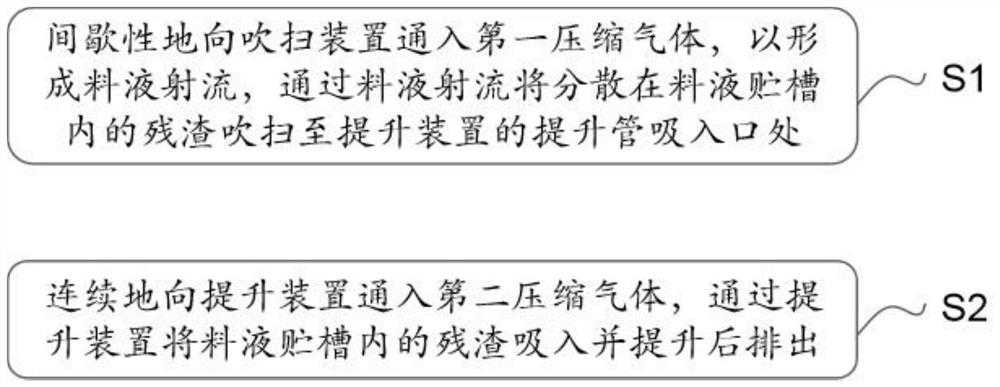
[0048] like figure 1 As shown, the present embodiment discloses a continuous slagging method, comprising:

[0049] S1, intermittently feed the first compressed gas into the purge device placed in the feed liquid in the feed liquid storage tank, so that the feed liquid entering the purge device is sprayed to form a feed liquid jet, and passes through the feed liquid jet Sweep the residue dispersed in the feed liquid storage tank to the suction port of the riser of the lifting device;

[0050] S2, continuously feed the second compressed gas into the lifting device, so as to suck the residue in the feed liquid storage tank through the suction port of the lifting pipe of the lifting device and discharge it after being lifted.

[0051]This embodiment also discloses a continuous slagging system, including a purge unit, a lifting unit and a control unit, the purge unit includes a purge device, the lifting unit includes a lifting device, the control unit includes a time controller, t...

Embodiment 2

[0054] like figure 1 As shown, the present embodiment discloses a continuous slagging method, comprising:

[0055] S1, intermittently feed the first compressed gas into the purge device placed in the feed liquid in the feed liquid storage tank, so that the feed liquid entering the purge device is sprayed to form a feed liquid jet, and passes through the feed liquid jet Sweep the residue dispersed in the feed liquid storage tank to the suction port of the riser of the lift device.

[0056] Further, step S1 specifically includes the following steps:

[0057] S101, injecting the first compressed gas into the compressed air tank until the gas pressure in the compressed tank reaches a preset pressure threshold and volume threshold.

[0058] In this embodiment, the first compressed gas is compressed air. The pressure threshold and volume threshold in the pressure tank refer to the pressure and gas volume of the first compressed gas required to completely (ideally) or mostly eject...

Embodiment 3

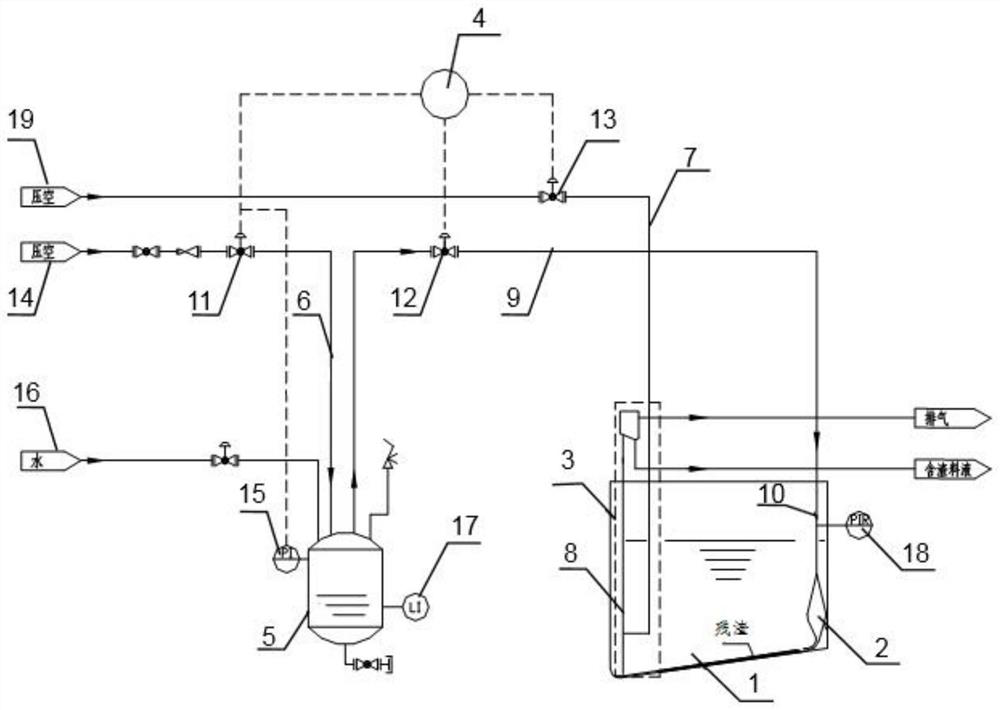
[0070] like figure 2 As shown, this embodiment discloses a continuous slagging system, which can be used in the continuous slagging method described in Example 1. The system includes a purging unit, a lifting unit and a control unit. The purging unit includes a purging device 2 , and the lifting unit includes a lifting device 3 .

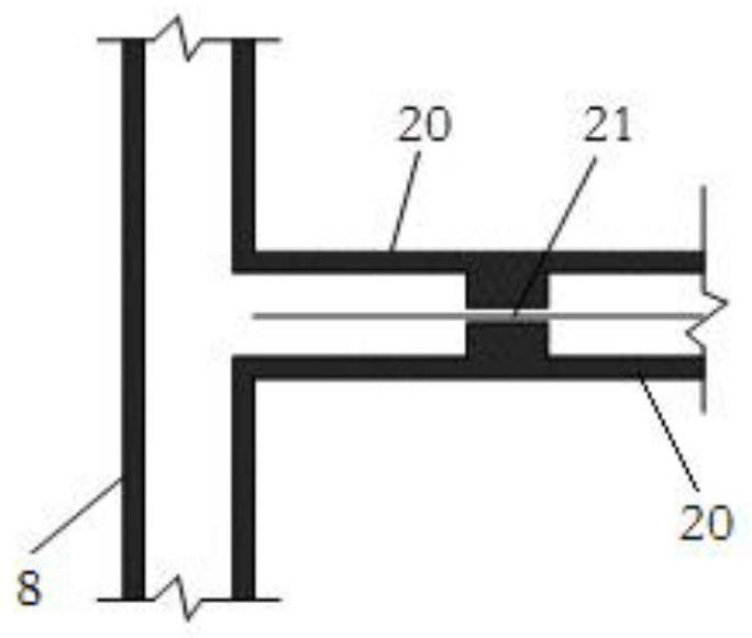
[0071] The purging device 2 includes a nozzle, and the lifting device 3 includes a second air inlet pipe 7 and a rising pipe 8, wherein the control unit is connected with the purging unit for controlling the introduction of the first compressed gas into the purging device 2, so that the entering The feed liquid in the purging device 2 is sprayed from the nozzle to form a feed liquid jet, and the residue dispersed in the feed liquid storage tank is blown to the suction port of the riser pipe 8 of the lift device 3 through the feed liquid jet; the control unit It is also connected with the lifting device 3, and is used to control the introduction of...


PUM


Abstract

The invention discloses a continuous deslagging method which comprises the following steps: S1, intermittently introducing first compressed gas into a purging device placed in feed liquid of a feed liquid storage tank so as to enable the feed liquid entering the purging device to be sprayed out to form feed liquid jet flow, and purging residues dispersed in the feed liquid storage tank to a risersuction inlet of the lifting device through the feed liquid jet flow; and S2, continuously introducing second compressed gas into the lifting device so as to suck residues in the feed liquid storage tank through a lifting pipe suction inlet of the lifting device, and discharging the residues after lifting. The invention further discloses a continuous deslagging system for the method. According tothe invention, stable and continuous deslagging can be realized, and the problems of violent vibration and the like are avoided.

Description

technical field [0001] The invention belongs to the field of nuclear technology, and in particular relates to a continuous slag discharge method and system for residues produced in the process of dissolving spent fuel reprocessing. Background technique [0002] During the continuous dissolution process of spent fuel reprocessing, the short pieces of sheared spent fuel are continuously added to the dissolver, and react with the nitric acid in the dissolver, and the dissolution reaction will continuously produce insoluble residues, which cannot be tolerated. The accumulation at the bottom of the flat tank of the dissolver may cause problems such as local heating and hardening of the bottom of the flat tank, so it needs to be discharged in time. [0003] At present, the deposited residue is mainly taken out through the cooperative operation of the purging device and the lifting device. However, the traditional purging device blows the residue to the residue inlet of the liftin...

Claims


Application Information

Patent Timeline
Patent Type & Authority Applications(China)
IPC IPC(8): G21C19/46G21F9/30
CPCG21C19/46G21F9/30Y02E30/30Y02W30/50
Inventor 逯迎春宋晓鹏吴志强侯留东陈勇李思凡陈琪庞臻
Owner CHINA NUCLEAR POWER ENG CO LTD
Why Eureka
Try Eureka