Three-axis relativistic klystron amplifier capable of suppressing non-rotational symmetric clutter mode

A non-rotational symmetry and relativistic technology, which is applied in klystrons, electron tubes with velocity/density modulation electron flow, discharge tubes, etc., can solve the problem of affecting the angular uniformity of the electric field in the gap of the injection cavity and the difficulty in increasing the output microwave pulse width of the device , injection of microwave amplitude and phase inconsistency, etc., to avoid the decline in the modulation depth of the electron beam, to facilitate long pulse operation, and to overcome the effect of space charge force

Active Publication Date: 2020-11-03
NAT UNIV OF DEFENSE TECH
View PDF9 Cites 11 Cited by
  • Summary
  • Abstract
  • Description
  • Claims
  • Application Information

AI Technical Summary

Problems solved by technology

This technical scheme verifies the feasibility of the three-axis relativistic klystron amplifier to achieve GW-level phase-locked high-power microwave output in the high frequency band, which has important reference significance for the design of high-gain relativistic klystron amplifier, but the technical scheme has the following Disadvantages: (1) A single three-gap cluster cavity has limited ability to modulate the high-current electron beam, and the modulation depth of the electron beam is only 102%, so the extraction cavity cannot efficiently convert the energy of the electron beam into microwave energy, resulting in the The efficiency is relatively low; (2) In order to improve the modulation depth of the electron beam, the power required for injecting microwave signals is relatively high, resulting in a relatively low gain of the device; (3) The injection cavity adopts a dual-port microwave injection structure, which is prone to two The amplitude

Method used


Image

  • Three-axis relativistic klystron amplifier capable of suppressing non-rotational symmetric clutter mode
  • Three-axis relativistic klystron amplifier capable of suppressing non-rotational symmetric clutter mode
  • Three-axis relativistic klystron amplifier capable of suppressing non-rotational symmetric clutter mode

Examples


Embodiment Construction

[0031] The accompanying drawings constituting the present application are used to provide further explanation of the present invention, and the exemplary embodiments of the present invention and their descriptions are used to explain the present invention, and do not constitute an improper limitation of the present invention.

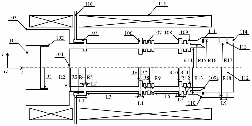
[0032] figure 1 A schematic structural diagram of the X-band triaxial relativistic klystron amplifier disclosed in the prior art mentioned in the background introduction; the structure includes a cathode seat 101, a cathode 102, an anode outer cylinder 103, an inner conductor 104, an injection cavity 105, a first Reflecting cavity 106, clustering cavity 107, second reflecting cavity 108, extraction cavity 109, tapered waveguide 110, feedback loop 111, electron beam collector 112, support rod 113, microwave output port 114, solenoid magnetic field 115, injection waveguide 116, the overall structure is rotationally symmetric about the central axis (ie the...


PUM

PropertyMeasurementUnit
Wall thicknessaaaaaaaaaa

Abstract

The invention belongs to the technical field of high-power microwaves, and discloses a three-axis relativistic klystron amplifier capable of suppressing a non-rotational symmetric clutter mode. The amplifier comprises a cathode seat 201, a cathode 202, an anode outer cylinder 203, an inner conductor 204, an injection cavity 205, a first reflection cavity 206, a first clustering cavity 207, a second reflection cavity 208, a second clustering cavity 209, a third reflection cavity 210, an extraction cavity 211, a conical waveguide 212, a feedback ring 213, an electron beam collector 214, a support rod 215, a microwave output port 216, a solenoid magnetic field 217 and an injection waveguide 218. The whole structure is in rotational symmetry relative to the central axis. Through the reasonabledesign of an electromagnetic structure of the amplifier, the defects that a lateral dual-port injection structure in an existing three-axis relativistic klystron amplifier is complex, non-rotationalsymmetric mode self-excited oscillation is difficult to completely inhibit from a physical mechanism and the like are overcome, and the three-axis relativistic klystron amplifier has good frequency-locking and phase-locking characteristics; the amplifier has important reference significance for designing a similar klystron amplifier required by high-power microwave space coherent power synthesis.

Description

technical field [0001] The invention relates to a microwave source device in the field of high-power microwave technology, in particular to a triaxial relativistic klystron amplifier (TRKA) capable of suppressing non-rotationally symmetric miscellaneous modes. Background technique [0002] High Power Microwave (HPM) usually refers to electromagnetic waves with a peak power greater than 100 MW and a frequency between 1 and 300 GHz. The high-power microwave source is the core component of the high-power microwave system. It converts the energy of the strong-current relativistic electron beam into microwave energy through the special electromagnetic structure inside the device, and then generates directional high-power microwave radiation through the transmitting antenna. The pursuit of high output microwave power is the main development direction in the field of high-power microwave technology. However, with the increase of output microwave power, the RF field strength in the ...

Claims


Application Information

Patent Timeline
IPC IPC(8): H01J25/10H01J23/213H01J23/36
CPCH01J23/213H01J23/36H01J25/10H01J2223/213H01J2223/36H01J2225/10
Inventor 巨金川周云霄张威党方超张军
Owner NAT UNIV OF DEFENSE TECH
Why Eureka
Try Eureka