Door handle module

A door handle and handle bracket technology is applied in the field of motor vehicle locking systems to achieve the effects of simple installation, flexible arrangement and installation.

Inactive Publication Date: 2020-11-03
KIEKERT AG
View PDF10 Cites 0 Cited by
  • Summary
  • Abstract
  • Description
  • Claims
  • Application Information

AI Technical Summary

Problems solved by technology

On the downside, however, there is no mechanical redundancy

Method used


Image

  • Door handle module
  • Door handle module
  • Door handle module

Examples


Embodiment Construction

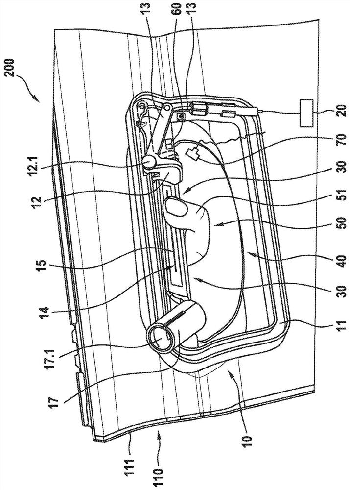
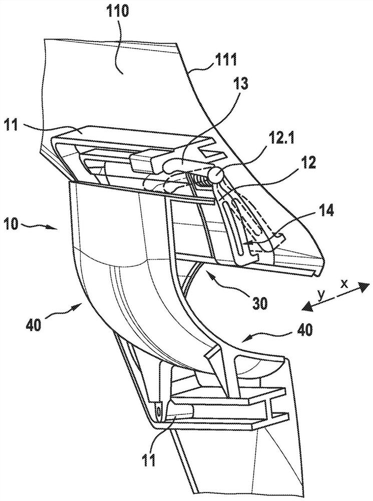
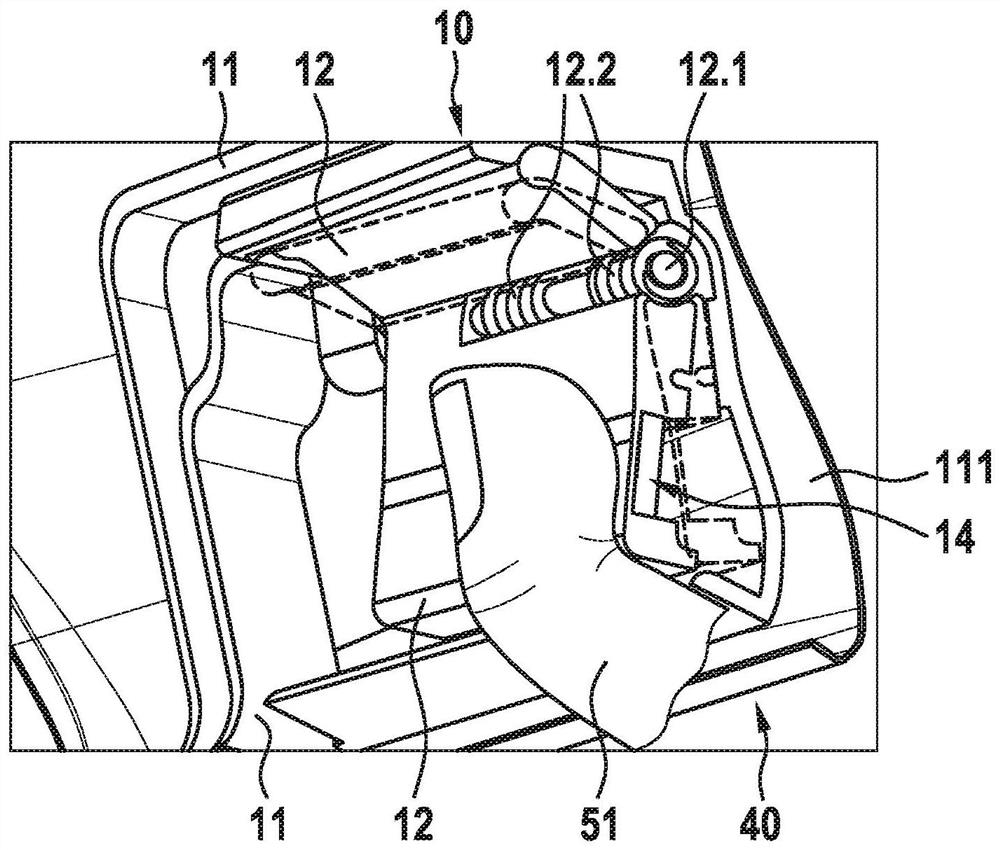
[0035] exist figure 1 A motor vehicle locking system according to the invention with a door handle module according to the invention is described in a first embodiment. The door handle module 10 is here mounted on a movable part 110 . The movable part 110 has a housing 111 , wherein the handle carrier 11 of the door handle module 10 is mounted on the housing 111 of the movable part 110 . In this case, the handle holder 11 is arranged on the housing 111 of the movable part 110 around the door handle groove 40 . Thus, the door handle groove 40 enables the user's hand or finger 51 to be inserted into the door handle groove and the handle 12 to be operated by the user's finger 51 . For this purpose, the handle 12 has an axis of rotation 12.1, wherein the handle 12 is figure 1 The center can be swung parallel to the housing 111 by the finger 51 . exist figure 1 This means that the handle 12 is designed as a rod and can be rotated around the axis of rotation 12.1 figure 1 Swip...


PUM


Abstract

The invention relates to a door handle module (10) for a movable part (110) of a vehicle (100), in particular for a side door, tailgate, bonnet or luggage compartment hatch, comprising a handle support (11) that can be mounted on the outer skin (111) of the movable part, a handle (12) mounted movably on the handle support (11) and having an actuation mechanism (13) that can be hidden at least in part by the outer skin (111), the actuation mechanism (13) being operatively connectable to a lock (20) or a lock drive so that an, in particular mechanical, actuation of the lock (20) of the movable part (110) can be performed, and further comprising a sensor unit (14) having at least one sensor element (15) in order to detect a user intention in an actuation region (30) of a door handle depression (40) of the movable part (110) so that the lock (20) or the lock drive is electrically actuatable in the actuation region (30) in the event that a user intention is identified.

Description

technical field [0001] The invention relates to a door handle module according to the preamble of independent claim 1 and to a motor vehicle locking system according to the independent system claim. Background technique [0002] Door handles and door handle modules for electrically operable locks enable the lock to be actuated by means of sensors arranged on the vehicle or on the door handle, wherein the sensor detects a user's desire to enter and unlocks the lock after authentication. However, it is disadvantageous that there is no mechanical redundancy. A door handle module of this type is known from DE 103 00 573 A1, in which a user's desire to open is detected by means of a sensor unit. However, in an emergency situation or when the vehicle is powered off, it is no longer possible to actuate the lock mechanically via the door handle. Contents of the invention [0003] The object of the invention is to at least partially eliminate the disadvantages known from the prio...

Claims


Application Information

Patent Timeline
Patent Type & Authority Applications(China)
IPC IPC(8): E05B81/76E05B81/90E05B81/78E05B17/10E05B77/04E05B85/06E05B85/18E05B85/10E05B79/20E05B81/80
CPCE05B17/10E05B77/04E05B79/20E05B81/77E05B81/78E05B81/80E05B81/90E05B85/06E05B85/10E05B85/18
Inventor T·班德尔M·埃格特
Owner KIEKERT AG
Why Eureka
Try Eureka