Movable fire extinguishing device

A fire extinguishing device and mobile technology, applied in electric vehicles, fire rescue, transportation and packaging, etc., can solve the problems of large water consumption, low fire extinguishing efficiency, economic loss, etc., to reduce property losses, simple structure, and protect personal safety Effect

Inactive Publication Date: 2020-11-06
CHINA ELECTRIC POWER RES INST +1
View PDF9 Cites 2 Cited by
  • Summary
  • Abstract
  • Description
  • Claims
  • Application Information

AI Technical Summary

Problems solved by technology

[0004] For fires at charging equipment and energy storage power stations, the current fire extinguishing method mostly uses foam fire extinguishing. This fire extinguishing method consumes a lot of water during the fire extinguishing process, and the fire extinguishing efficiency is low.
After research, it is found that for the fire extinguishing of energy storage equipment, both fire extinguishing and cooling need to be considered at the same time. Only the fire extinguishing operation may sometimes cause re-ignition, which will cause greater economic losses and casualties.

Method used


Image

  • Movable fire extinguishing device
  • Movable fire extinguishing device

Examples


Embodiment 1

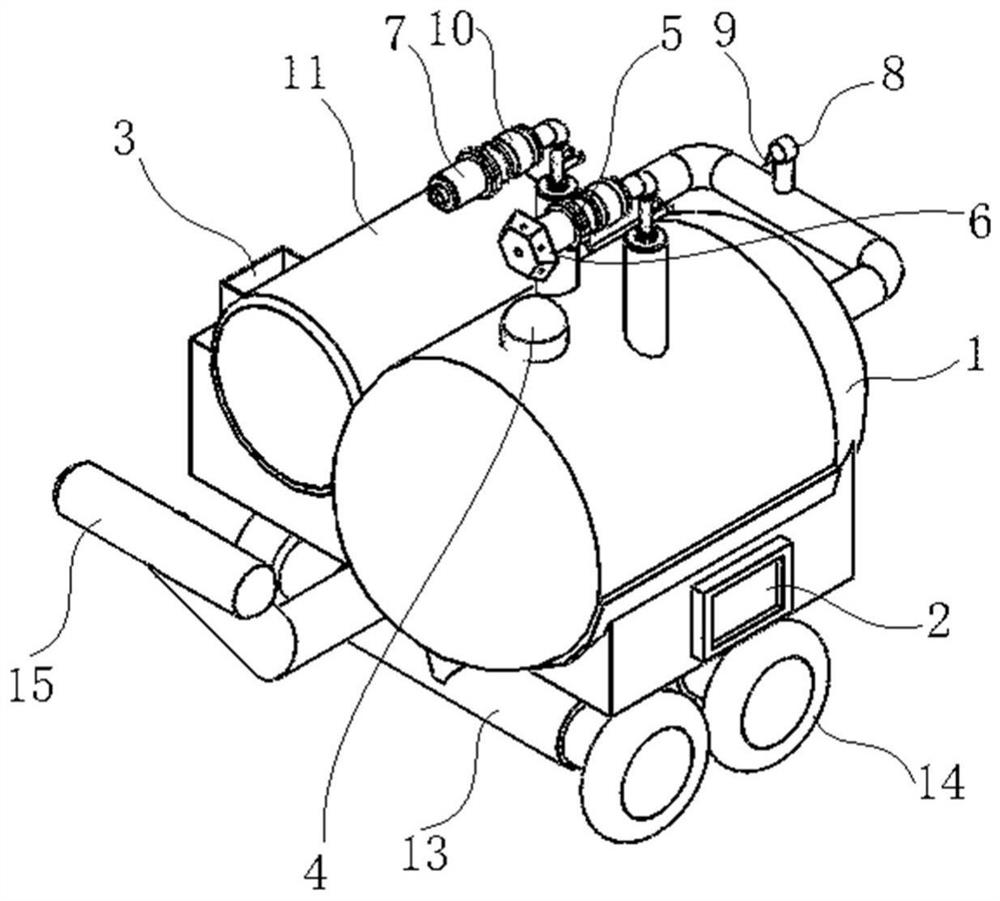
[0043] see figure 1 When the present invention adopts the mobile fire extinguishing device with external pressurization as the driving mode, four wheels 14 are arranged at the bottom of the bottom plate 13 of the mobile auxiliary platform, one side of the bottom plate 13 is provided with a control panel 2, and the other side is provided with a wheel for placing water. Water belt box 3. A liquid storage cylinder 1 and a gas storage cylinder 11 are placed side by side on the mobile auxiliary platform. One end of the liquid storage cylinder 1 and the gas storage cylinder 11 are connected through a U-shaped connecting pipeline, and the U-shaped connecting pipeline is A decompression valve 8 and a solenoid valve 9 are provided, and a T-shaped handrail 15 is provided on the bottom plate 13 near the other end of the liquid storage cylinder 1 and the gas storage cylinder 11, and the handrail 15 is bent upward. The top of the liquid storage cylinder 1 is respectively provided with a t...

Embodiment 2

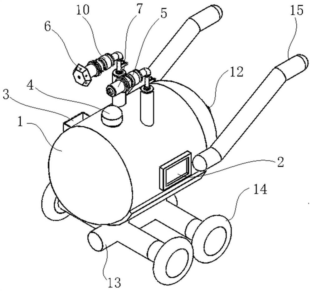
[0045] see figure 2 , when the present invention uses internal pressurization as the mobile fire extinguishing device of the driving mode, four wheels 14 are arranged at the bottom of the bottom plate 13 of the mobile auxiliary platform. A liquid storage cylinder 1 is placed horizontally on the mobile auxiliary platform, a control panel 2 is provided on one side of the liquid storage cylinder 1, and a hose box 3 for placing a hose is provided on the other side, and the two sides of the liquid storage cylinder 1 are symmetrical A Z-shaped handrail 16 is provided, and the liquid storage cylinder 1 is provided with a booster port 12 near the handrail 16. The top of the liquid storage cylinder 1 is respectively provided with a tank liquid port 4, an atomizing spray gun and a DC spray gun. The atomizing spray gun includes one end The first connecting pipeline communicated with the liquid storage cylinder 1, and the ball valve, solenoid valve, internal connection interface and atom...


PUM


Abstract

The invention discloses a movable fire extinguishing device. The movable fire extinguishing device comprises a movable auxiliary platform capable of moving, and a gas-liquid combined fire extinguishing device arranged on the movable auxiliary platform. The gas-liquid combined fire extinguishing device comprises a liquid storage unit for storing a liquid fire extinguishing agent, and a pressurizingunit connected with the liquid storage unit and used for carrying out gas pressurizing conveying on the liquid fire extinguishing agent. According to the movable fire extinguishing device, the gas-liquid combined fire extinguishing device is adopted, and fire extinguishment can be carried out on charging equipment and energy storage power stations of electric cars; and due to the fact that the gas-liquid combined fire extinguishing device has cooling and fire extinguishing effects, the movable auxiliary platform assists the gas-liquid combined fire extinguishing device in moving, and the cooling and fire extinguishing efficiency can be effectively improved, so that the property loss is reduced to the maximum extent, and the personal safety of the masses is protected.

Description

technical field [0001] The invention belongs to the technical field of fire fighting, and in particular relates to a mobile fire extinguishing device. Background technique [0002] At present, with the rapid development of electric vehicles, the direction of charging piles for electric vehicles has also emerged. As of January 2020, the number of charging piles in my country has reached 1.243 million, an increase of nearly double that of the same period last year. Considering the development speed of the electric vehicle industry, charging infrastructure such as charging piles still have good development prospects in the future. [0003] However, with the sudden increase in the number of electric vehicles, safety accidents are emerging one after another, and some of them occur during the charging of electric vehicles. In April 2020, a new energy vehicle caught fire during charging in Xishuangbanna, Yunnan. Not only did it completely burn itself out, but it also caused varyi...

Claims


Application Information

Patent Timeline
Patent Type & Authority Applications(China)
IPC IPC(8): A62C3/07A62C3/16A62C31/00A62C31/28B60L53/302
CPCA62C3/07A62C3/16A62C31/00A62C31/28B60L53/302Y02T10/70Y02T10/7072Y02T90/12
Inventor 杨凯赖铱麟刘皓张明杰
Owner CHINA ELECTRIC POWER RES INST
Why Eureka
Try Eureka