Table concentrator flow guide control system based on visual servo and table concentrator flow guide control method

A technology of diversion control and visual servoing, which is applied in the field of shaking table diversion control system based on visual servoing, can solve the problems such as the influence of technical proficiency and professional quality of mineral processing accuracy, the need to improve the automation level, and the difficulty of improving mineral processing accuracy. To achieve the effect of long-term operation accuracy and guarantee, improve mineral processing efficiency and accuracy, and improve the degree of automation

Inactive Publication Date: 2020-11-06
湖南大奇智能科技有限公司 +2
View PDF10 Cites 1 Cited by
  • Summary
  • Abstract
  • Description
  • Claims
  • Application Information

AI Technical Summary

Problems solved by technology

[0002] Shaker beneficiation is a kind of gravity beneficiation method, and it is a common equipment for the primary selection of fine-grained ore. Traditional shakers are mostly manned shakers. In the actual production process, frequent manual inspections are still required to adjust the position of the deflector. Diverting the different ore belts separated by the shaking table into the corresponding ore separation tank requires a large workload, and the beneficiation accuracy is affected by the technical proficiency and professional quality of the on-site workers. It is difficult to improve the ore beneficiation accuracy, and the automation level needs to be improved.

Method used


Image

  • Table concentrator flow guide control system based on visual servo and table concentrator flow guide control method
  • Table concentrator flow guide control system based on visual servo and table concentrator flow guide control method
  • Table concentrator flow guide control system based on visual servo and table concentrator flow guide control method

Examples


Embodiment Construction

[0056] The present invention will be further described below in conjunction with the accompanying drawings and embodiments.

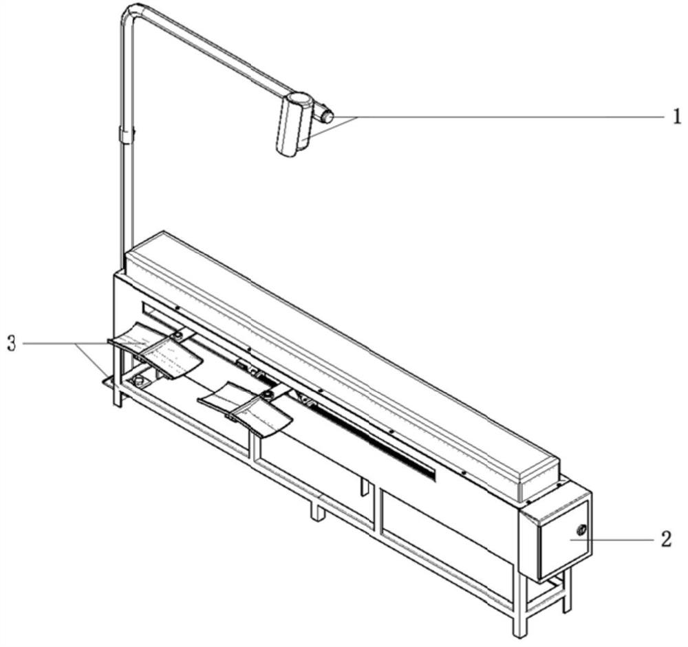
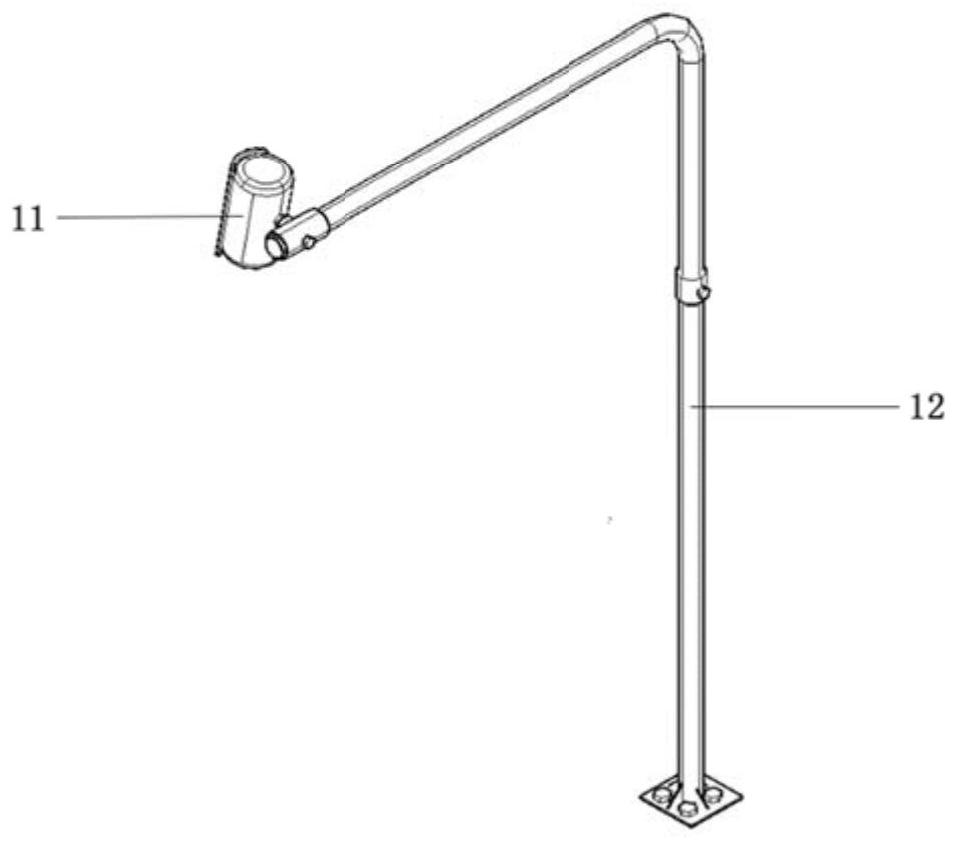
[0057] Such as figure 1 As shown, a shaker diversion control system based on visual servoing includes a visual acquisition unit 1 for collecting real-time images, an operation control unit 2 for control, and a servo diversion mechanism for diversion of the shaker device 3.

[0058] Such as Figure 4 As shown, the servo deflector mechanical device 3 includes a deflector housing 31, a servo slide group 32, a positioning mark 33, and a deflector baffle 34. The deflector housing 31 is made of stainless steel, and its exterior is coated with antirust paint. The structure is compact, and the deflector housing 31 is used to install and protect other components of the servo deflector mechanical device 3; On the slide group 32 and can move on the servo slide group 32, the guide baffle 34 is provided with a positioning mark 33 for determining the position coor...


PUM


Abstract

The invention discloses a table concentrator flow guide control system based on a visual servo. The table concentrator flow guide control system comprises a visual acquisition unit, an operation control unit and servo flow guide mechanical devices, wherein the servo flow guide mechanical devices comprise flow guide device shells, servo sliding table sets, positioning marks and flow guide baffles,the servo sliding table sets are installed on the flow guide device shells, the flow guide baffles are installed on the servo sliding table sets and can move on the servo sliding table sets, and the positioning marks are arranged on the flow guide baffles. The visual acquisition unit acquires ore belt distribution on the surface of the table concentrator and positioning mark position coordinate pictures of the servo flow guide mechanical devices, the operation control unit operates an ore belt distribution recognition and positioning mark positioning algorithm and outputs control signals to drive the servo sliding table sets and drives the flow guide baffles to adjust the positions, and different ore belts on the surface of the table concentrator are guided into corresponding ore separating grooves through the flow guide baffles, so that automatic ore separation is achieved, the automation degree of a concentrating plant is improved, the ore separation efficiency and precision are improved, and the labor cost is greatly reduced.

Description

technical field [0001] The invention relates to the field of mineral processing, in particular to a visual servo-based shaking table diversion control system and a shaking table diversion control method. Background technique [0002] Shaker beneficiation is a kind of gravity beneficiation method, and it is a common equipment for the primary selection of fine-grained ore. Traditional shakers are mostly manned shakers. In the actual production process, frequent manual inspections are still required to adjust the position of the deflector. Diverting the different ore belts separated by the shaking table into the corresponding ore separation tank requires a lot of work, and the ore dressing accuracy is affected by the technical proficiency and professional quality of the on-site workers. It is difficult to improve the ore dressing accuracy, and the automation level needs to be improved. How to use simple devices to replace the work tasks of on-site personnel on the basis of the ...

Claims


Application Information

Patent Timeline
Patent Type & Authority Applications(China)
IPC IPC(8): B03B13/00B03B5/04
CPCB03B13/00B03B5/04
Inventor 卢明覃左栋刘黎辉王仓谢永芳黄昆江云生邓毓弸王锦煜
Owner 湖南大奇智能科技有限公司
Why Eureka
Try Eureka