Automatic cut-off machine used for band saw blade grinding production and machining

An automatic cut-off and band saw blade technology, which is applied in metal processing equipment, manufacturing tools, metal sawing equipment, etc., can solve laborious and labor-intensive problems, and achieve the effect of simple and convenient cutting and blanking, and simple and convenient movement

Active Publication Date: 2020-11-06
江苏美特森切削工具有限公司
View PDF5 Cites 0 Cited by
  • Summary
  • Abstract
  • Description
  • Claims
  • Application Information

AI Technical Summary

Problems solved by technology

[0007] In the production process, it is also necessary to cut the band saw blade to a certain length, so that the two sides of each saw blade can be welded together, and the welding joint is annealed, sandblasted, and finally a circle of saw blades is formed; but the existing saw blades are being cut At this time, the end of the saw blade needs to be fixed and cut at a certain length, and then the end of the saw blade needs to be repositioned, cut again, and repeated to complete the truncation of the saw blade, but each time the end needs to be fixed again. laborious

Method used


Image

  • Automatic cut-off machine used for band saw blade grinding production and machining
  • Automatic cut-off machine used for band saw blade grinding production and machining
  • Automatic cut-off machine used for band saw blade grinding production and machining

Examples


Embodiment 1

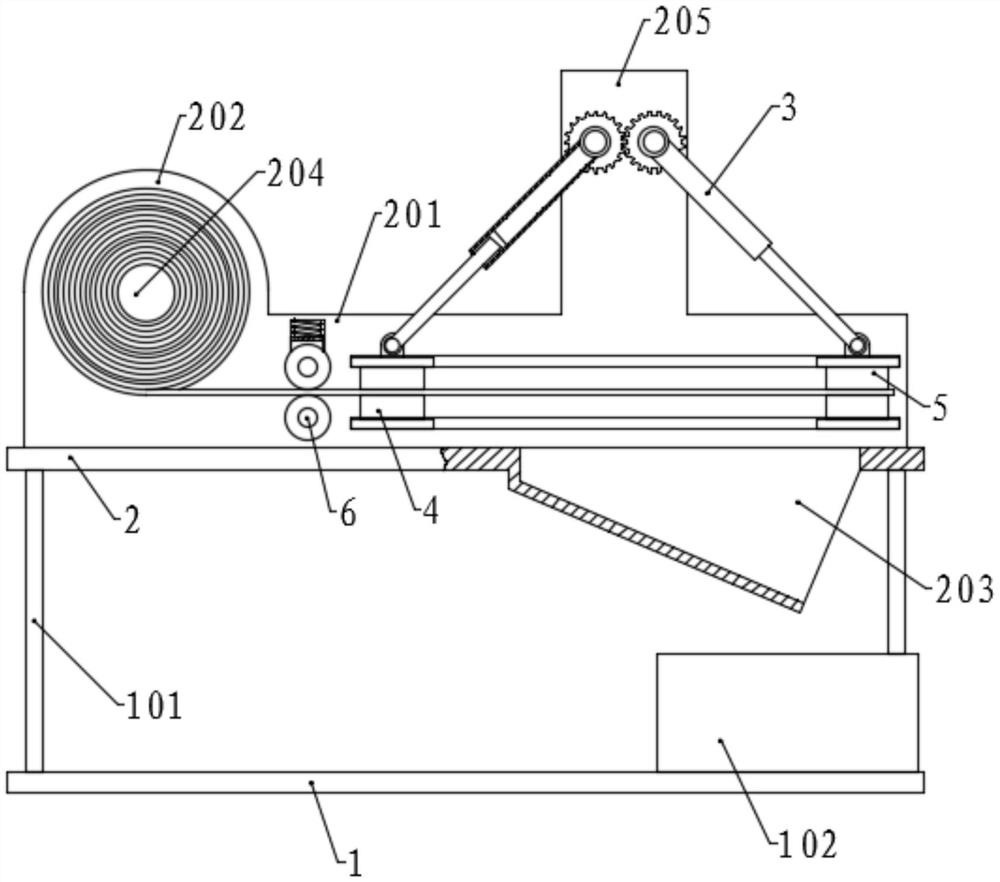
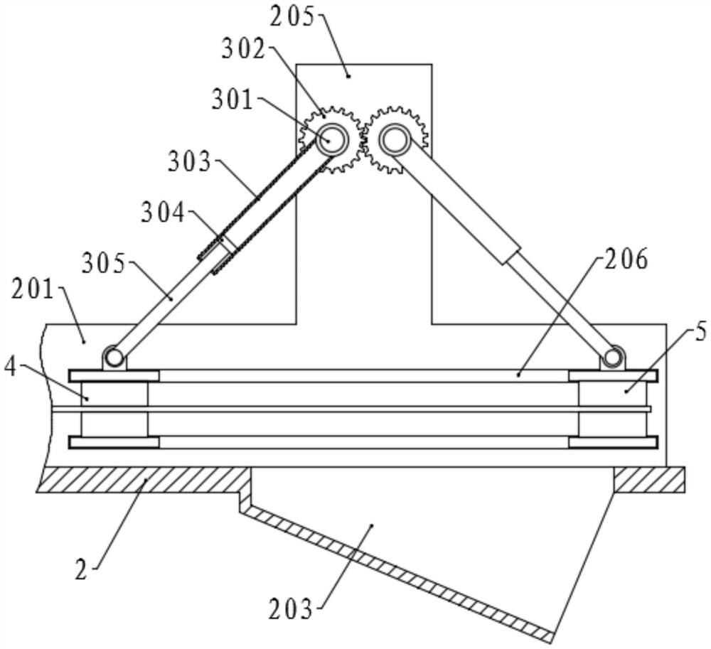
[0057] Please refer to the accompanying drawings, the present invention provides a technical solution: an automatic cutting machine for band saw blade grinding, production and processing, including a base 1, vertical support rods 101 are fixed at the four corners of the top surface of the base 1, and the support rods 101 The top of the workbench 2 is fixed together, the right section of the workbench 2 is provided with a hopper 203, the bottom surface of the chute 203 is inclined, and the base 1 is provided with a collection box 102 at the position corresponding to the chute 203, Both sides of the workbench 2 are symmetrically fixed with a vertical first side plate 201, a vertical extension plate 205 is fixed in the middle of the top of the first side plate 201, a second side plate 202 is fixed at the left end, and the second side plate 202 The top of is set as a semicircle;

[0058] The first side plate 201 is provided with two horizontal slide grooves 206, and the first posi...

Embodiment 2

[0072]The structure of this embodiment is basically the same as that of Embodiment 1. The difference is that a plurality of clamping blocks 707 are uniformly fixed on the right side ends of the upper pressing plate 705 and the lower pressing plate 701 on the first positioning assembly 4, and the width of the clamping blocks 707 is smaller than steel. The length of the clamp block 707 on the lower platen 701 is greater than that of the clamp block 707 on the upper platen 705, and the top surface of the clamp block 707 on the lower platen 701 is provided with a cutting groove 708 corresponding to the position of the cutting knife 8, and the second positioning The upper pressing plate 705 on the assembly 5 and the left end of the lower pressing plate 701 are provided with a block groove 709 at the position corresponding to the clamping block 707 , and the length of the block groove 709 on the lower pressing plate 701 is longer than that of the upper pressing plate 705 .

[0073] W...

Embodiment 3

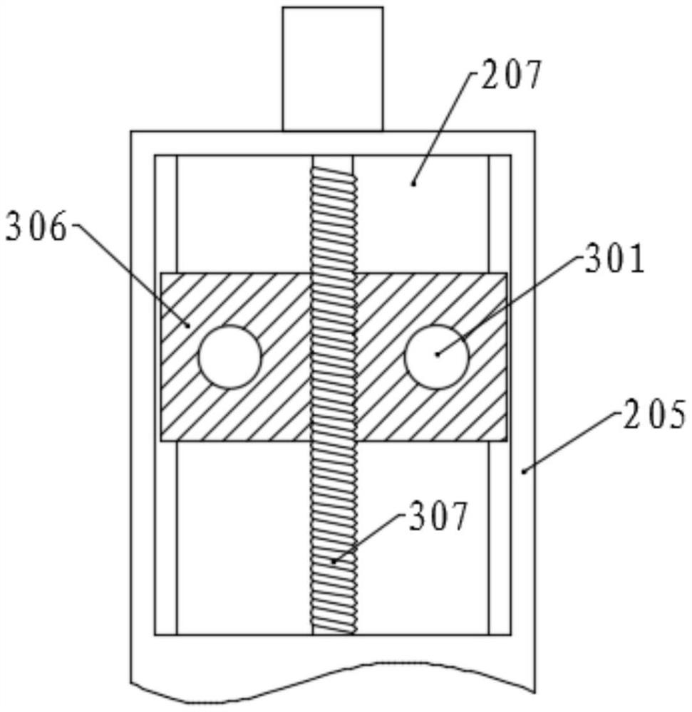
[0075] The structure of this embodiment is basically the same as that of Embodiment 1. The difference is that an adjustment slot 207 is provided on the top of the extension plate 205, and an adjustment block 306 is slidably connected to the adjustment slot 207. The ends of the two rotating shafts 301 are connected to the adjustment block. 306 is rotatably connected, and the middle thread of the adjustment block 306 is connected with a vertical threaded shaft 307, and the threaded shaft 307 is rotatably connected with the top surface and the bottom surface of the lift groove, and the top stretches out of the adjustment groove 207, and is connected with a motor.

[0076] When it is necessary to adjust the maximum distance between the ends of the telescopic rods 305 on both sides, that is, the cut-off length of the steel bar, start the motors on the top of the extension plates 205 on both sides to rotate the threaded shaft 307, and the adjustment block 306 will be driven by the scr...


PUM


Abstract

The invention discloses an automatic cut-off machine used for band saw blade grinding production and machining. The automatic cut-off machine comprises a work table. The work table is provided with adischarge tank. First side plates, second side plates and extension plates are fixed to the two sides of the work table. Each first side plate is provided with slide grooves and are connected with a first positioning assembly and a second positioning assembly through the slide grooves. A rotation assembly is arranged on each extension plate. According to the automatic cut-off machine, by means ofa guide assembly, the height positions of steel bars can be located in the middles of the first positioning assembly and the second positioning assembly, and the steel bars are kept horizontal in themovement process; by means of the first positioning assembly, the end portions of the steel bars are fixed, and the steel bars are driven to get close to the second positioning assembly; after the steel bars are fixed through the second positioning assembly, the first positioning assembly is released, and the first positioning assembly and the second positioning assembly reset; the steel bars arecut off through a cut-off assembly, the steel bars which are cut off are released by the second positioning assembly, and the steel bars fall into a collection box through the discharge tank; and steel bar cut-off and discharge are easy and convenient.

Description

technical field [0001] The invention relates to the technical field of band saw blade production and processing, in particular to an automatic cutting machine for grinding, production and processing of band saw blades. Background technique [0002] Band saw blades consist of a tough, sharp-toothed blade tensioned in a frame and are used for cutting metal and other shaped materials. Band saw blades are widely used, generally used in mechanical processing industry, machinery manufacturing industry, automobile service industry, metal mining industry, etc. Therefore, first of all, it is necessary to choose a suitable band saw blade to cut the material, so as to achieve the best The best cutting effect, and the selection of the saw blade according to the cutting material. For steel with a large diameter, it is necessary to use a coarse-toothed saw blade for cutting. Otherwise, it is best to choose a relatively suitable fine-toothed saw blade, and to maintain the equipment regular...

Claims


Application Information

Patent Timeline
Patent Type & Authority Applications(China)
IPC IPC(8): B23D65/00
CPCB23D65/00
Inventor 肖建民
Owner 江苏美特森切削工具有限公司
Why Eureka
Try Eureka