Vertical take-off and landing aircraft with universal tilt rotors and control method thereof
A vertical take-off and landing, tilt-rotor technology, applied in vertical take-off and landing aircraft, aircraft, aircraft control and other directions, can solve the problems of poor flight response sensitivity, poor flight flexibility, difficult to control, etc., and achieve the flight action response is sensitive and timely. , easy to control, small footprint for take-off and landing
- Summary
- Abstract
- Description
- Claims
- Application Information
AI Technical Summary
Problems solved by technology
Method used
Image


Examples
Embodiment 1
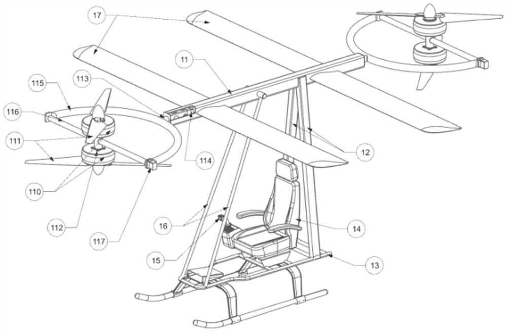
[0036] figure 1 It is a structural diagram of the vertical take-off and landing aircraft capable of universally tilting the rotor of the present embodiment.
[0037] combined with figure 1 , a vertical take-off and landing aircraft capable of universally tilting the rotor provided in this embodiment, including an aircraft body, a rotor, a tilting mechanism, a driving mechanism and a control mechanism.
[0038] In specific implementation, the aircraft body includes a longitudinal support rod 11 and two relatively inclined vertical support rods 12; the tops of the two relatively inclined vertical support rods 12 are installed in the middle of the longitudinal support rod 11 about The two sides of the rear position, wherein, the installation position relationship between the two relatively inclined vertical support rods and the longitudinal support rod can be adjusted according to the center of gravity; the bottom of the two relatively inclined vertical support rods 12 is connec...
Embodiment 2
[0058] attached figure 2 It is a structural diagram of the vertical take-off and landing aircraft capable of universally tilting the rotor of the present embodiment.
[0059] combined with figure 2 As shown, the vertical take-off and landing aircraft capable of universally tilting the rotor in this embodiment includes an aircraft body, a rotor, a tilting mechanism, a driving mechanism and a control mechanism.
[0060] In a specific implementation, the aircraft body includes a nacelle 21, two fixed wings and a landing gear 28, and the two fixed wings are respectively installed at the front and rear of the nacelle; the landing gear 28 is installed at the bottom of the nacelle 21.
[0061] In this embodiment, the two fixed wings are the front wing 22 and the rear wing 23 respectively. Specifically, the nacelle 21 is installed in the middle of the front wing 22 and the rear wing 23 , the front wing 22 is installed at the front of the nacelle 21 , and the rear wing 23 is instal...
Embodiment 3
[0073] attached image 3 It is a structural diagram of the vertical take-off and landing aircraft capable of universally tilting the rotor of the present embodiment.
[0074] combined with image 3 As shown, the vertical take-off and landing aircraft capable of universally tilting the rotor in this embodiment includes an aircraft body, a rotor, a tilting mechanism, a driving mechanism and a control mechanism.
[0075] In a specific implementation, the aircraft body includes a nacelle 31 , three fixed wings and a landing gear 39 . These three fixed wings are front wing 32, middle part wing 33 and rear wing 34 respectively; Nacelle 31 is installed in the middle position of three wings, and front wing 32 is installed in the front part of cabin 31, and middle part wing is installed In the middle of the nacelle 31 , the rear wing 34 is installed at the rear of the nacelle 31 ; the landing gear 38 is installed at the bottom of the nacelle 31 .
[0076] In this embodiment, two til...
PUM
 Abstract
Description
Claims
Application Information
 - R&D
- Intellectual Property
- Life Sciences
- Materials
- Tech Scout
- Unparalleled Data Quality
- Higher Quality Content
- 60% Fewer Hallucinations
Browse by: Latest US Patents, China's latest patents, Technical Efficacy Thesaurus, Application Domain, Technology Topic, Popular Technical Reports.
© 2025 PatSnap. All rights reserved.Legal|Privacy policy|Modern Slavery Act Transparency Statement|Sitemap|About US| Contact US: help@patsnap.com